
So this is a story of a boy meeting a girl, and they lived happily ever after. The end. Well, that is what I hope for, at least. However, before the happily ever after there were a couple (ok, a lot) of highlights along the way. And this is one of them specifically, how I became the luckiest man alive when my partner said yes to my marriage proposal, and this blog is how I went about it.
Being the self appointed ultimate nerd, I wanted to do something that encapsulates all my talents, hobbies, and interests coding, AI, computer graphics, and art. And so my eight month or more journey began.
I know I wanted to do something special and rather unique, something other than the usual run of the mill McDonald’s burger proposal. I’m not apologizing to anyone who proposed in this manner.
I had some initial ideas on how to propose, from shining a laser based image into a huge sand dune, learning how to program an ESP32 board to create a light curtain, or a juggling giraffe with a sign around its neck. However, on a more practical side of thing, I always wanted to see if I could create a caustic refraction image. Well, that is what I called it, but the full name according to the paper is “Poisson Based Continuous Surface Generation for Goal Based Caustics.”
See the paper here if you want to know more about it:
http://nishitalab.org/user/egaku/tog14/continuous_caustics.pdf
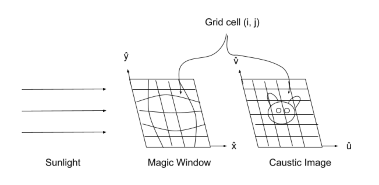
If reading a whole paper is too time consuming, below is the just how it works. The magic math creates a 3d object that is warped in such a way that the light shining through it is bent just right so that when it hits a wall it forms an image. See image below.
Here is the git repo if you want to try doing this yourself:
https://github.com/dylanmsu/poisson_caustic_design
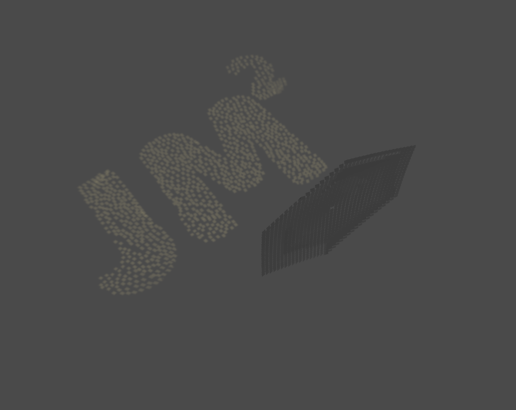
The idea was to create a 3D model with the words “Marry Me,” which I would then use to project onto a wall at a special location. Below you can see the words being warped to create the 3D model.

The issue, however, arose when I created the model and used a physically based rendering (PBR) engine. (Yes, I had to look this up.) In short, it can simulate how light would travel through or bounce off an object in a physically accurate way. When I created a test scene with the 3D model, it seemed that you would need to be very close to the wall to show the image correctly. I know other people have solved this issue, however, not in this case. And I did not want to go searching even more to try and get this working on a larger scale, as I’ve already spent about a month on this idea alone. This is not even mentioning the hassle of trying to physically create the object and playing around with things like the refractive index to get an image to show.
Below is a render from the Git repo showing their version, which came out much better than mine.
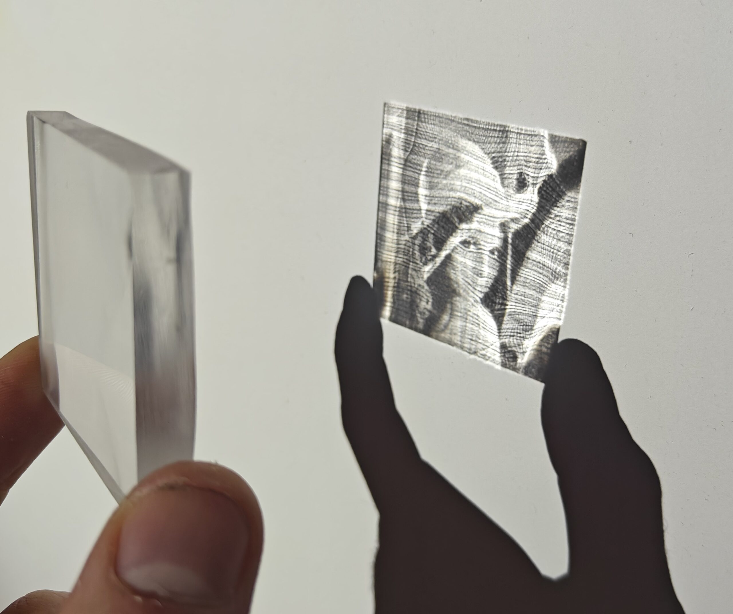
Here is an actual object the researchers created, and as you can see, you still need to keep this very close to the wall to actually make out the original image. That being said, just being able to do this blows my mind. Imagine showing this to someone ten or twenty years ago. Witchcraft, I tell you!
Well, in the end I decided not to go with this approach, as holding a little cube close to a wall and saying “Look,” then proposing did not seem grand enough for what I wanted. I mean, you only do this once (or twice, etc.) in your life. I then decided to try something else. Instead of refracting light, I wanted something that would reflect it. This way I should be able to reflect the light onto a surface as big as I wanted. The main idea I had was to first create a cube with a rough random surface on one side. If I could get light reflecting on it, I would then see what image (random spots at first) was produced. Then I would update the 3D object with some more random geometry and see if the image looked more like the image I wanted. I have some experience in genetic algorithms, so I was planning to use this approach to automate the process. The idea was that, over a couple of thousand iterations, I would then get an object with geometry that would reflect light in such a way as to form an image on a wall or on the ground. This seems easy in theory. In practice, not so much.
Mistuba
After doing some research I came across Mistuba. In short it’s a PBR that was only code based, no IDE or anything user friendly that you could use your mouse with in sight. Hey, I’m pretty good with coding and working with command lines, etc., so how hard could it be?
For more information on what Mistuba is capable of, feel free to visit the link below, as well as some examples of what the software can do when someone who really knows their stuff is in the driver’s seat.
https://mitsuba.readthedocs.io/en/stable/src/inverse_rendering/caustics_optimization.html
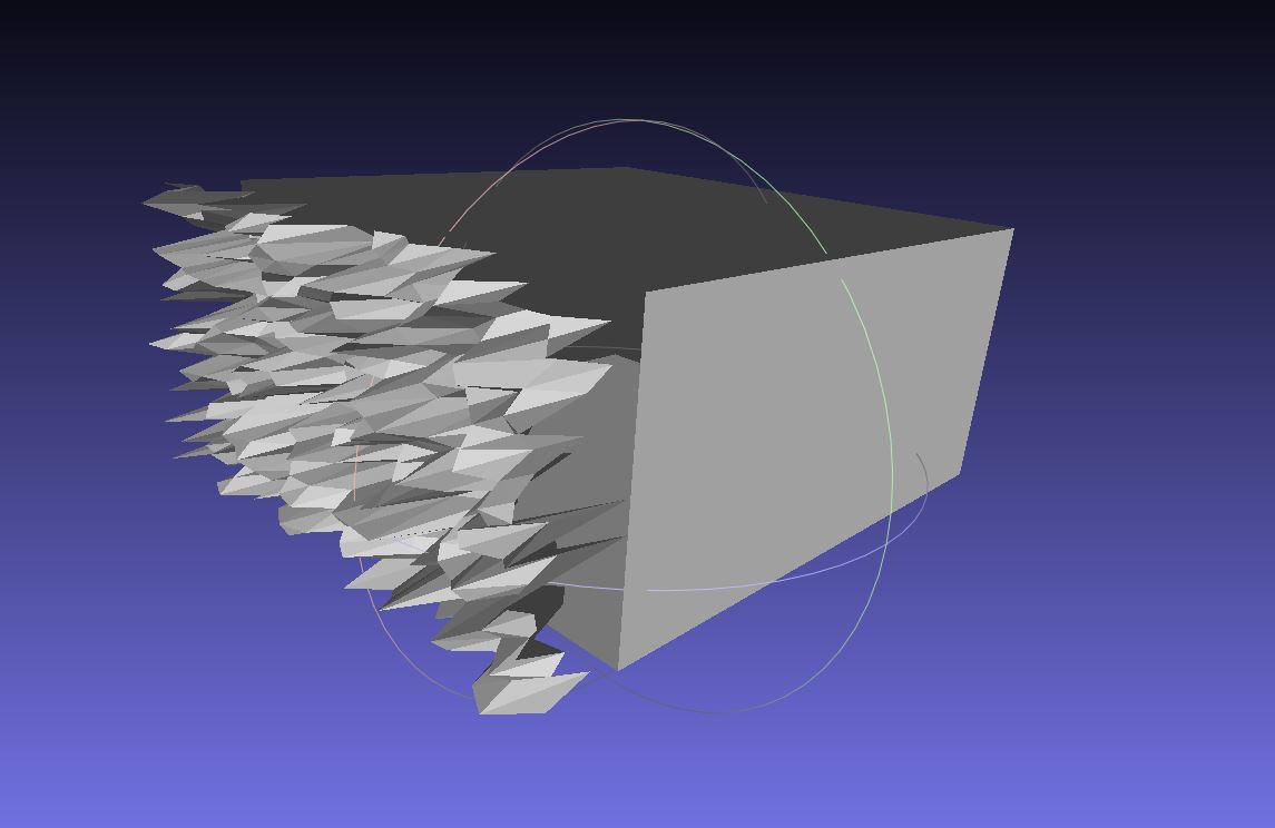
Well, it turns out you might need to be a light transport researcher with multiple PhDs and years of experience to get anything close to what you see above. Below is my version of the 3D cube with some randomness added. Keep in mind this all was done with very precise code; every angle, light source and material was one or multiple lines of code. I know this looks like a five year old found MS Paint and said “Look, Mommy, pretty!”, but this took me a couple of weeks just to get to this point. And yes, I will admit I kind of rage quit at this point. Even after reaching out to the creator Mistuba (who was not really in the mood to assist), I was not able to make any headway.
Blender
But no worries. There are other applications that can also do the same. It can render light accurately and has the option to edit anything via code. So along came Blender. It’s a very popular free 3D tool that you can use for almost any 3D task you can think of. Blender is a very good PBR and I still cannot imagine its free!
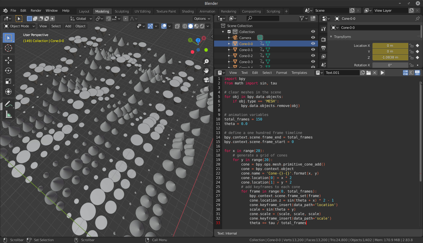
So again I created a script that Blender could read to first create a 3D object with a rough surface on one side and import it into a Blender scene.
I had to also install an additional render engine called Luxcore Render, as the base Blender could not render the reflections correctly, but in the end I managed to get light reflecting off the generated cube. I only had to adjust every single setting I could find, read, and watch way too many YouTube videos to get to this point.
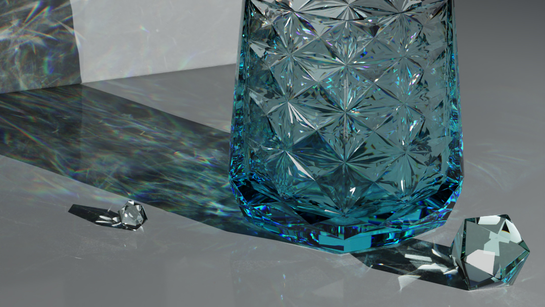
Just for reference, below is another screenshot (not mine) that shows the power of creating a 3D object via code.
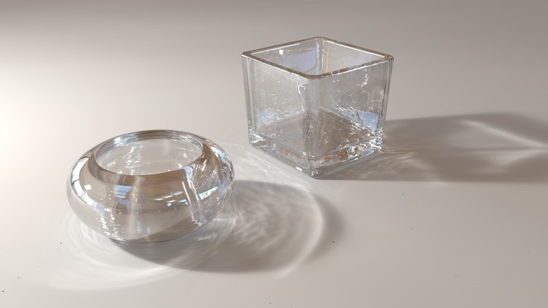
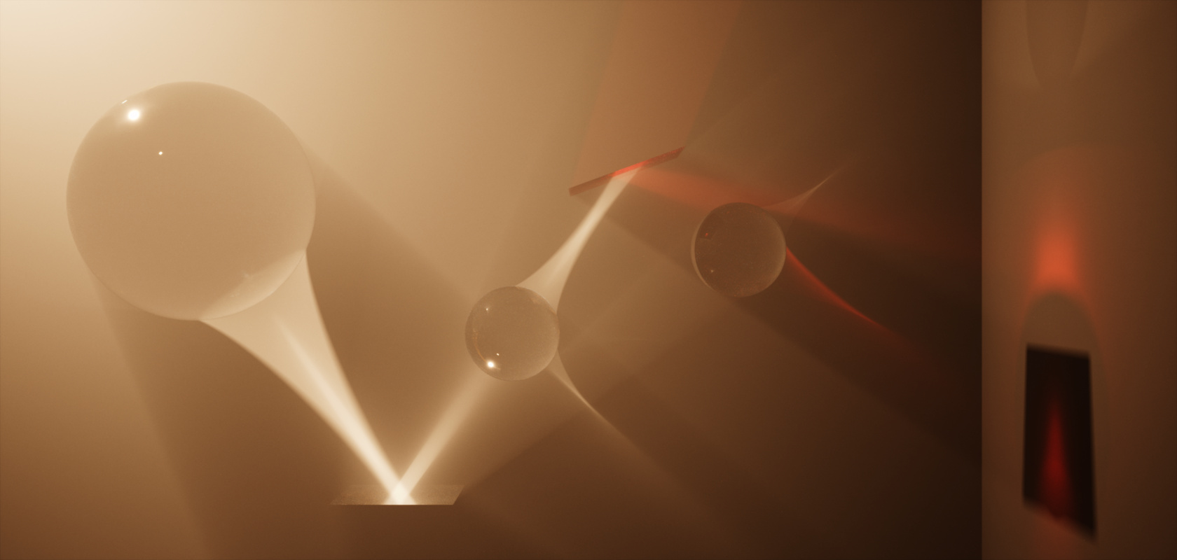
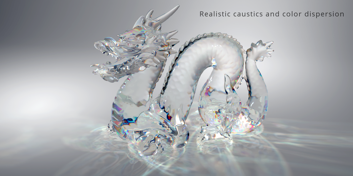
And here are some visuals one can create if you know what you are doing.
Unreal Engine
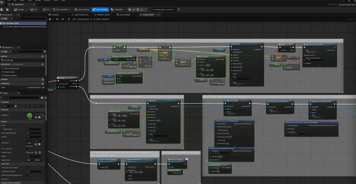
Next I tried the same approach using Unreal Engine. I had even worse luck with it than Blender. I know it’s also a very powerful tool; however, I have only used it in the past, mostly for small games or to create virtual reality environments. Unreal can be scripted as well, however I’ve never tried that and have only used the node based system in the past (example below), and I was still trying to get anything close to reflecting light. My obstacle here was that when searching for how to make an object reflective and reflect light, I kept running into “how to make mirrors” in Unreal Engine. Granted, since this is, for the most part, a game engine, I guess a lot of people want to create mirrors where the game character can see itself in real time.
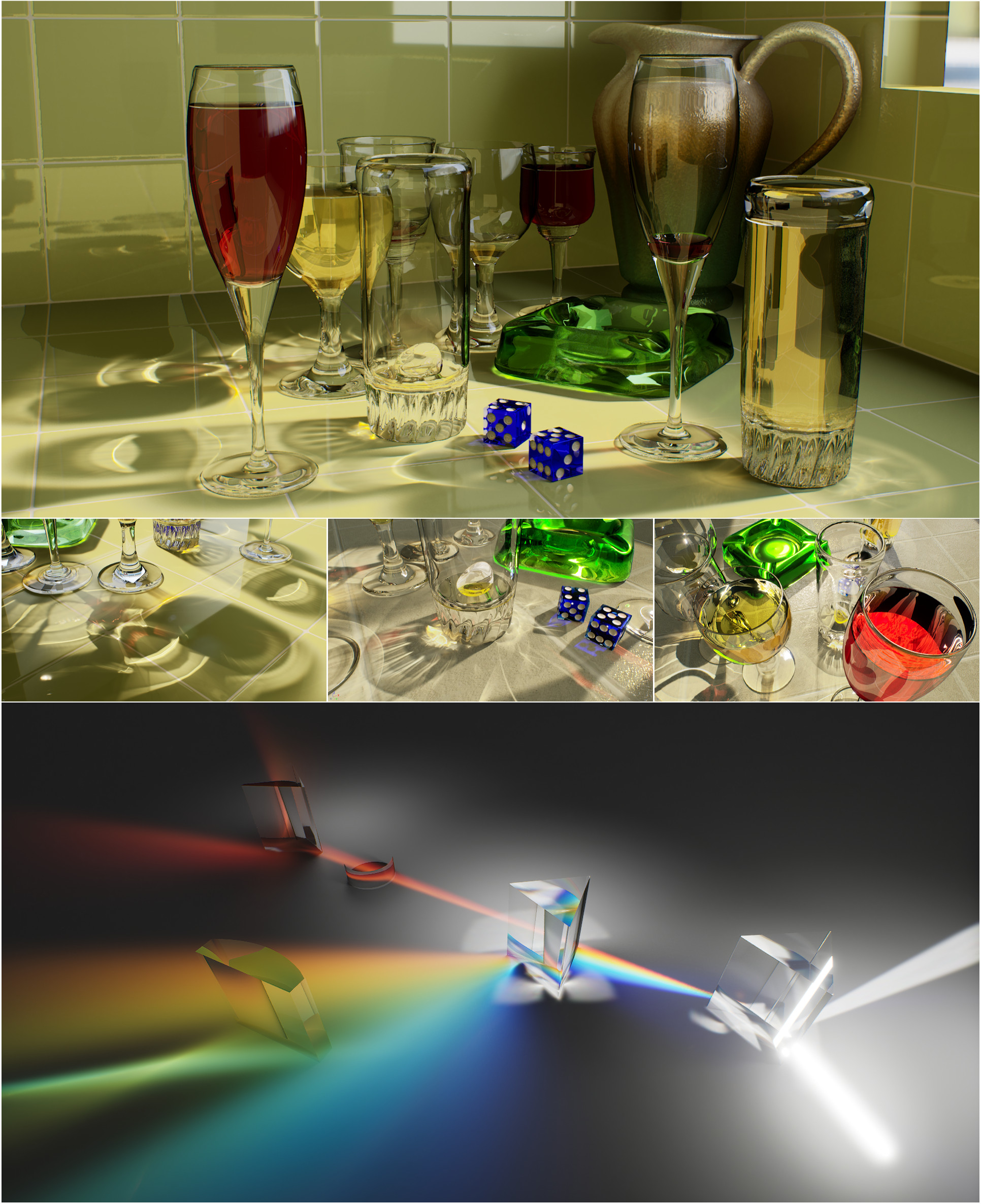
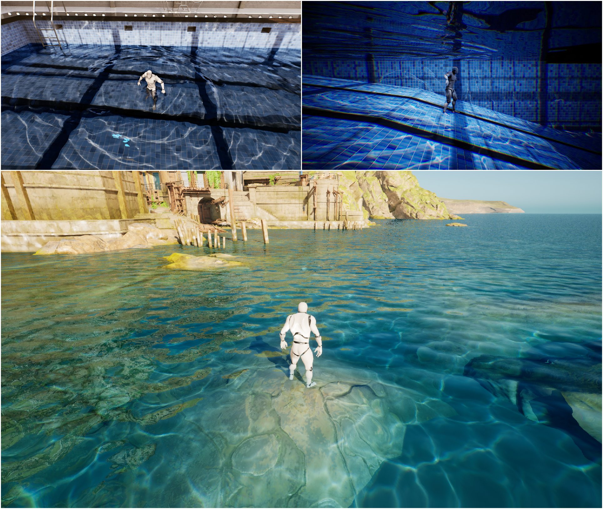
Again, for reference, this is what is possible if you really know what you are doing. These show mostly caustics and not light being reflected directly, yet another reason why I had to call it quits trying to make Unreal do something it was not really meant to do.

So all the applications can do what I wanted to do if I struggled long enough with it. The problem was that integrating a basic genetic algorithm into them was a bit (a lot) complicated. I understand programming and scripting, so that was not the issue. The issue was telling the programs to do what I wanted only via code and not via the GUI that 99% of people use. With a couple more months of watching YouTube videos, yelling at GPT and Claude, and trial and error, I’m sure I would have found a way to make one of these programs do what I wanted. However, I like my sanity (the little bit I still have left) and decided to skip the white coat where you hug yourself and find another way.
Ben Bartlett
This is when I came across a post from Ben Bartlett who used mirrors to reflect light to spell out words (or anything you want). I still would have liked to have one object with a curved surface that will reflect shapes, but that code and method was not available to me and I’ve already spent a couple of months testing ways NOT to do things.
Below is Ben’s Github and the original notebook I based all my work on. Ben, if you ever read this, THANK YOU!!!!
https://github.com/bencbartlett
https://github.com/bencbartlett/3D-printed-mirror-array/blob/main/mirror_array.ipynb
Below is an extract from Ben’s notebook explaining the process and idea much better than I could:
The basic idea here is that we have an array of mirrors forming a hexagonal grid. Each mirror is located with its centroid at some point in space, and we want for it to reflect a ray of sunlight to a pixel at some location on the ground (or any other focal plane). Since we know where each mirror is, where each corresponding target is, and where the sun is, we can solve for how each mirror needs to be oriented in 3D space in order to reflect the sunlight onto its corresponding target.
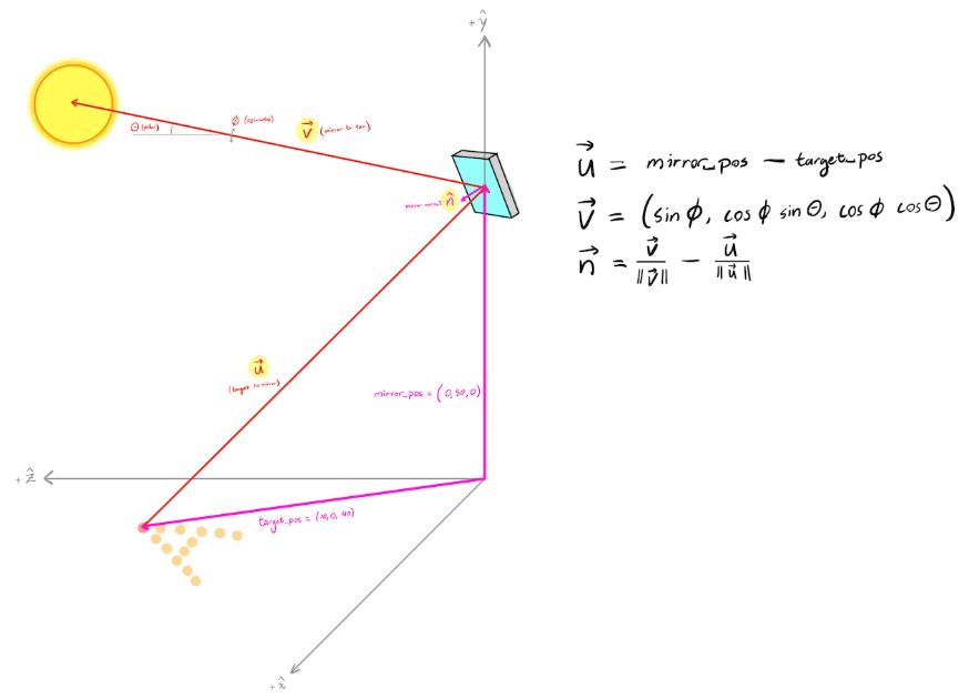
Consider just a single mirror and a single target pixel. The center of the mirror has coordinates located at some vector mirror_pos, and the center of the target pixel is at target_pos. Let’s define vectors such that mirror_pos – target_pos is the vector pointing from the target to the mirror center, and is the vector pointing in the direction of the sun (a point source placed at infinity). Here we’re assuming the sun is at an inclination of from the horizon and that the azimuthal angle relative to the mirror is .
Since the reflected angles are the same as the incident angles for a mirror, the normal vector of the mirror just needs to bisect these two vectors and , so we have that :
In other words, how to calculate the angle of each mirror so that it would form a point on the ground corresponding to an image or a set of predetermined points. Well, this is awesome! In Ben’s original notebook you had to input the coordinates of each point manually; you could use an external website, but everything was still very manual. Claude and I updated the code to use an image as input, generate a ton of points, and then reduce the number of points to the number of mirrors you wanted. I could not choose any number, because the way Ben set up the hexagonal grid you could only choose from a set number of points:
1, 7, 19, 37, 61, 91, 127, 169, 217, 331, 397, 469, 547, 631, 721, 817, 919, 1027 … and so on. Any number in between would mess with the way the hexagon shape was generated.
So off I went, created a test image to play with, and, being super optimistic and very naïve, I decided to try with 1027 points. I mean, why not? This is going to work perfectly the first time around and be done in a week!

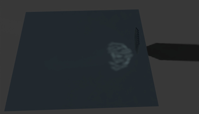
After updating Ben’s code to use some newer libraries, some bug fixing (that I introduced) and tweaking, I was ready to see my first test object. I created the object and imported it into a demo version of KeyShot and voilà! Messy blobs! I was a bit confused and disappointed not to see the perfect image straight off the bat. Oh well, it must be a bug or error I made somewhere along the way. Long and short of it, after rechecking all the code and changes I made, it turned out I just needed to move the object a bit higher up in the air! Wow, who would have thought! Not me, apparently!
After some additional playing around with the settings, the angle of the virtual sun, I managed to get a very decent reflection of the image I wanted! I was rather excited at this point and was ready to start printing my first real object to see if it would work in real life! Thinking back I can only shake my head to how uninformed and naïve I was. But you know we all learn, some just need to bump their head more than others before getting it, I guess.
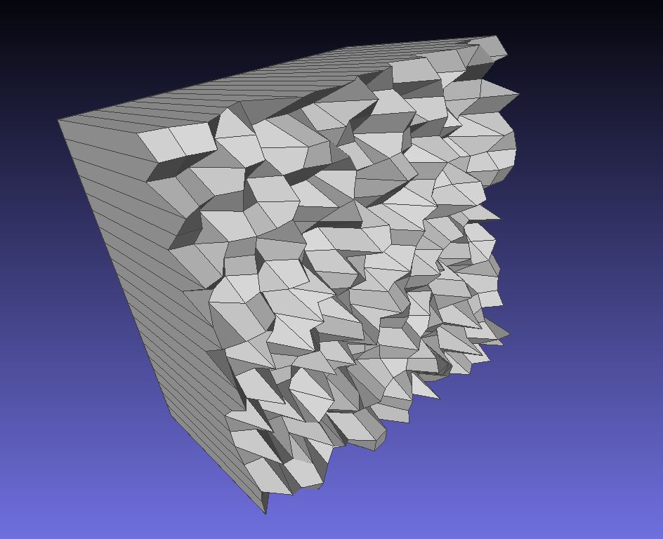
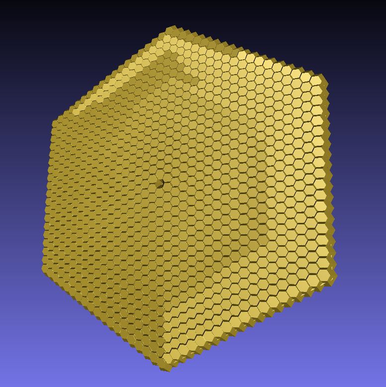
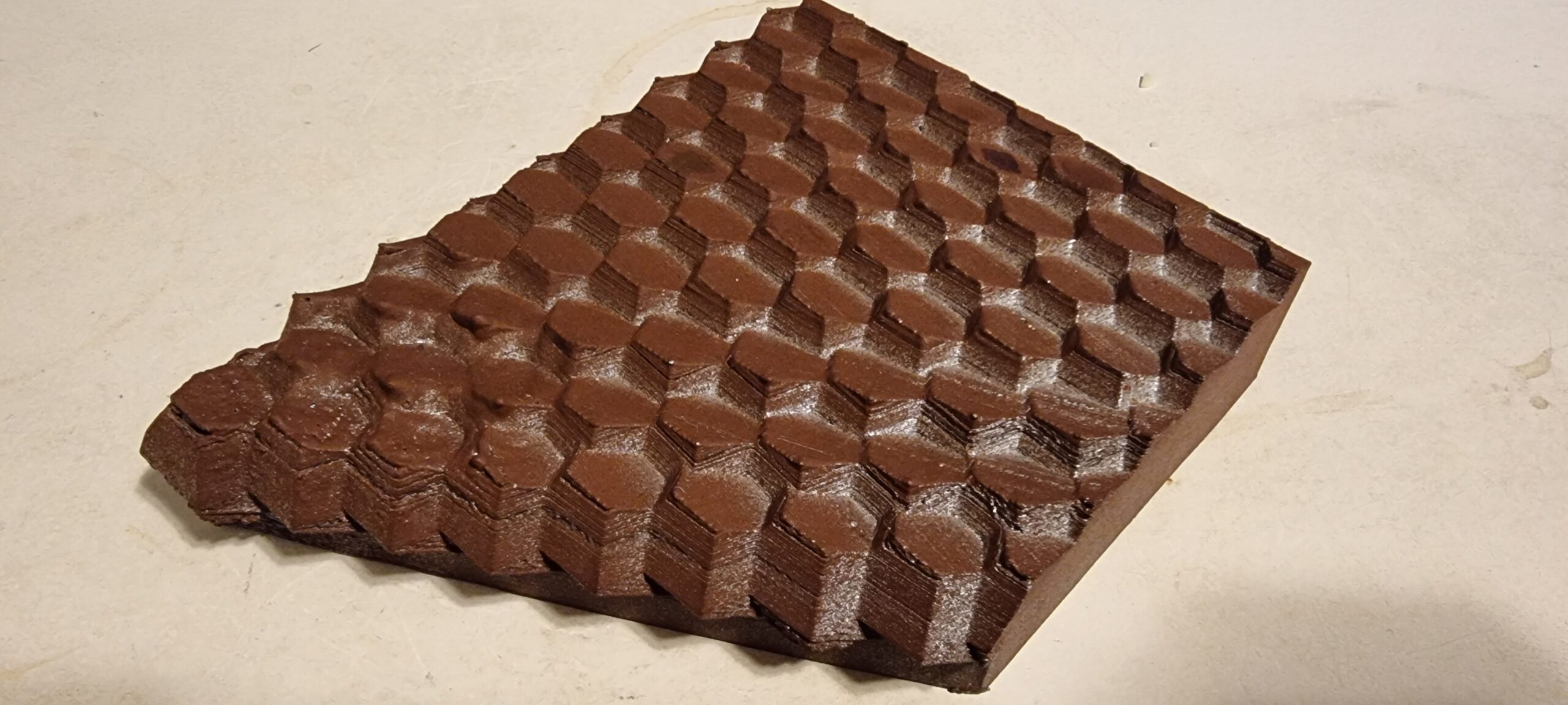
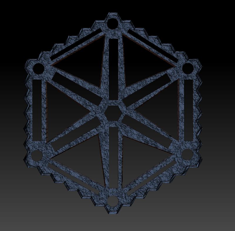
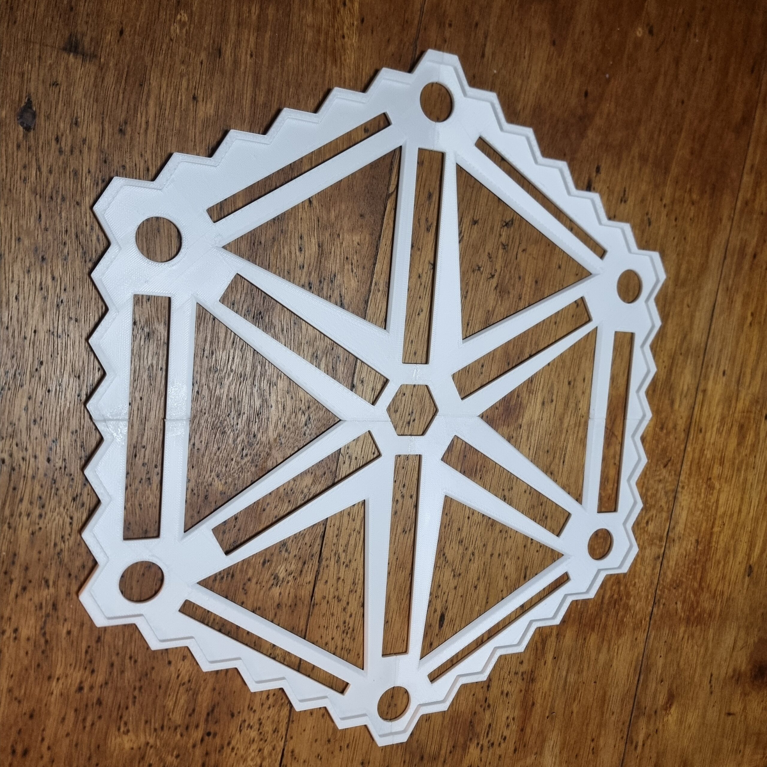
Here is the 3D model the code produced. You can see there are some overlap here and there, but that did not seem to be much of an issue. You can also see very clearly how some regions of hexagons are angled way differently than others to form the reflected shape. I’ve gone through this whole process and I still find it mind blowing, someone (Ben) thought of something like this and actually made it work!
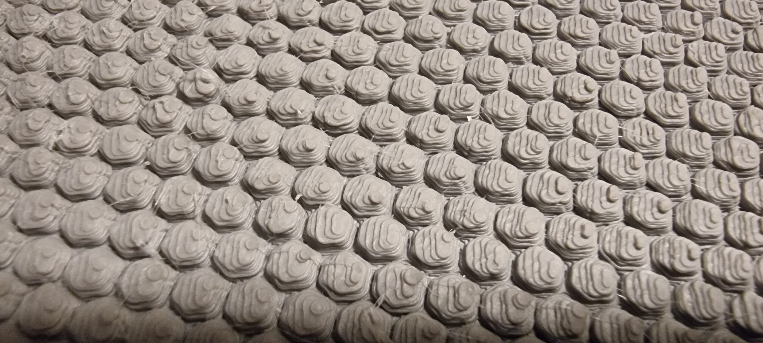
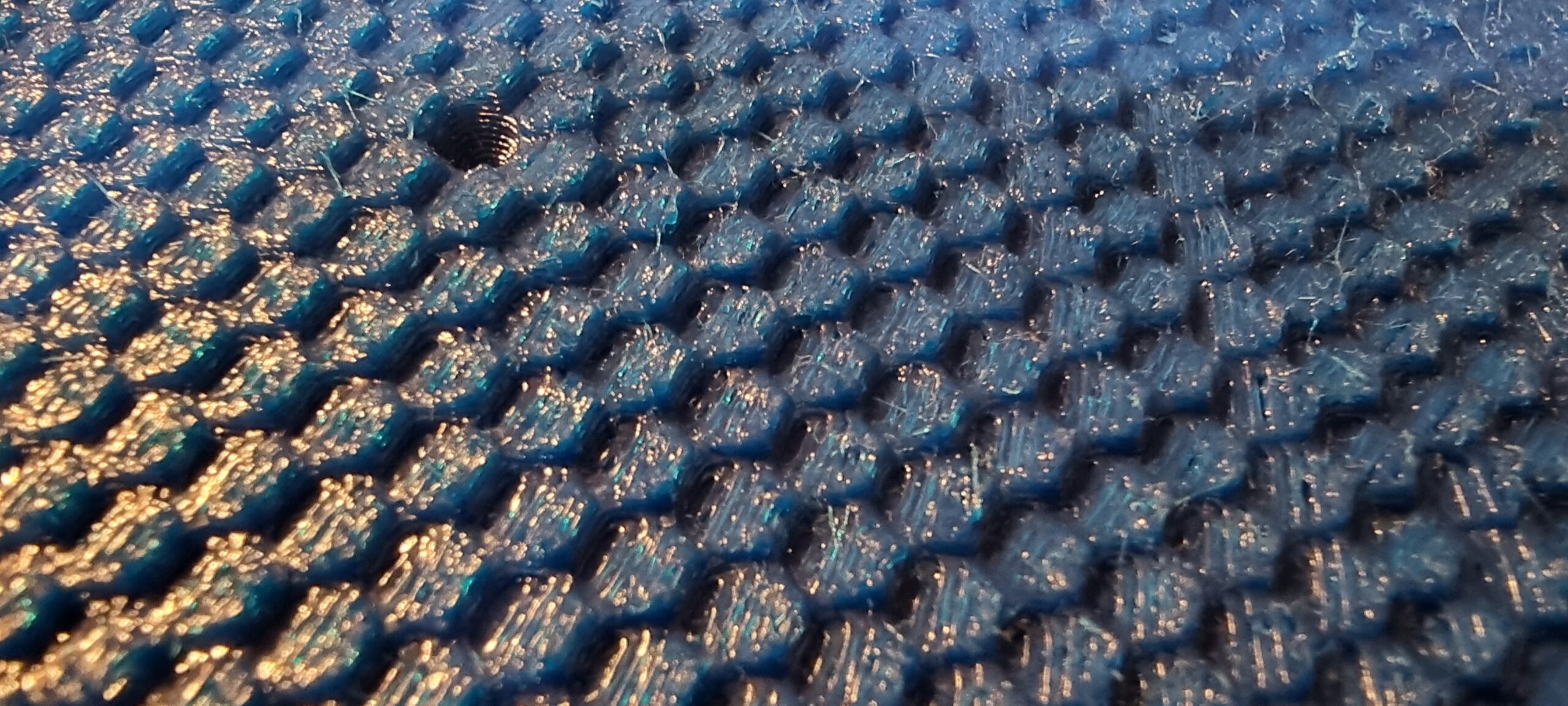
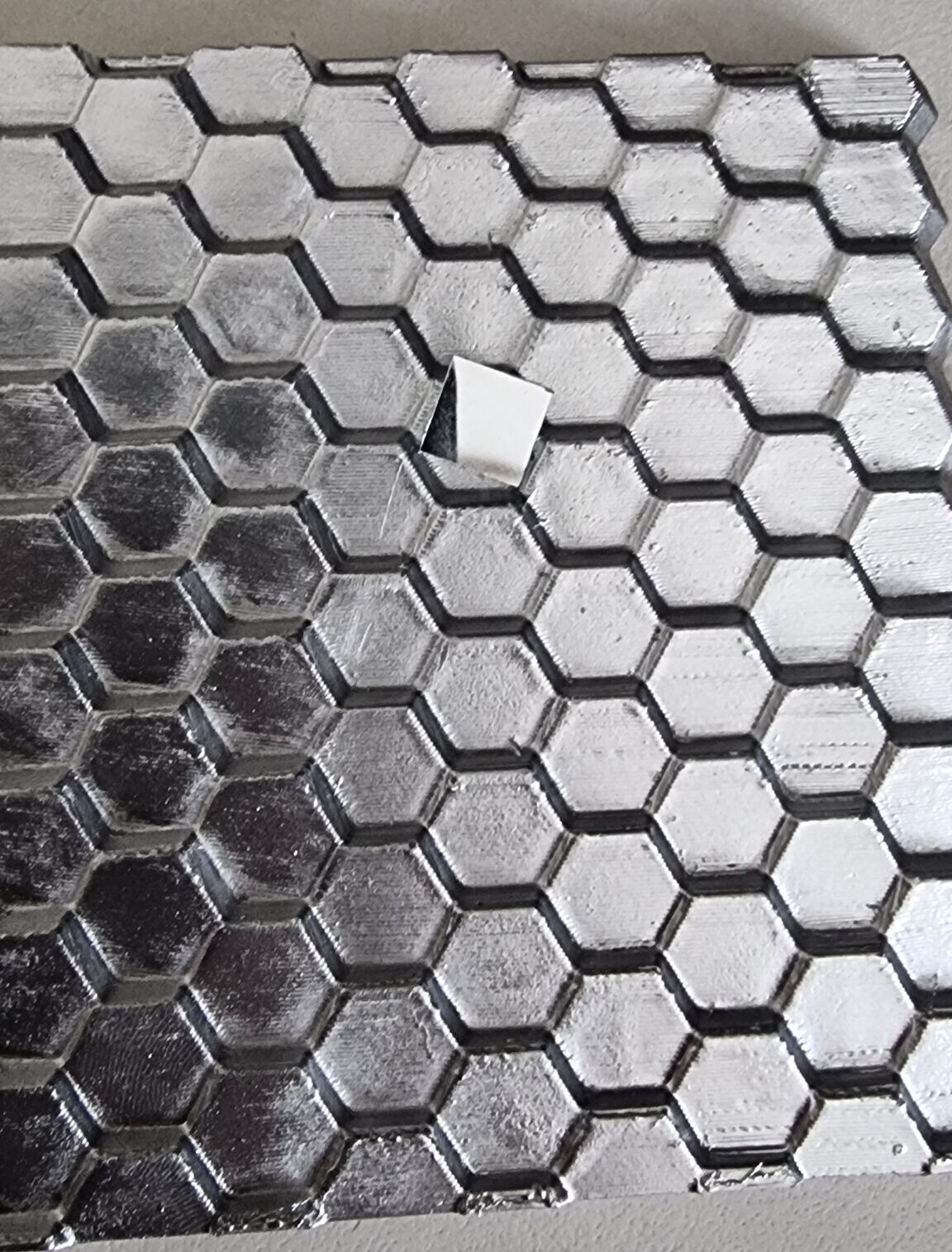
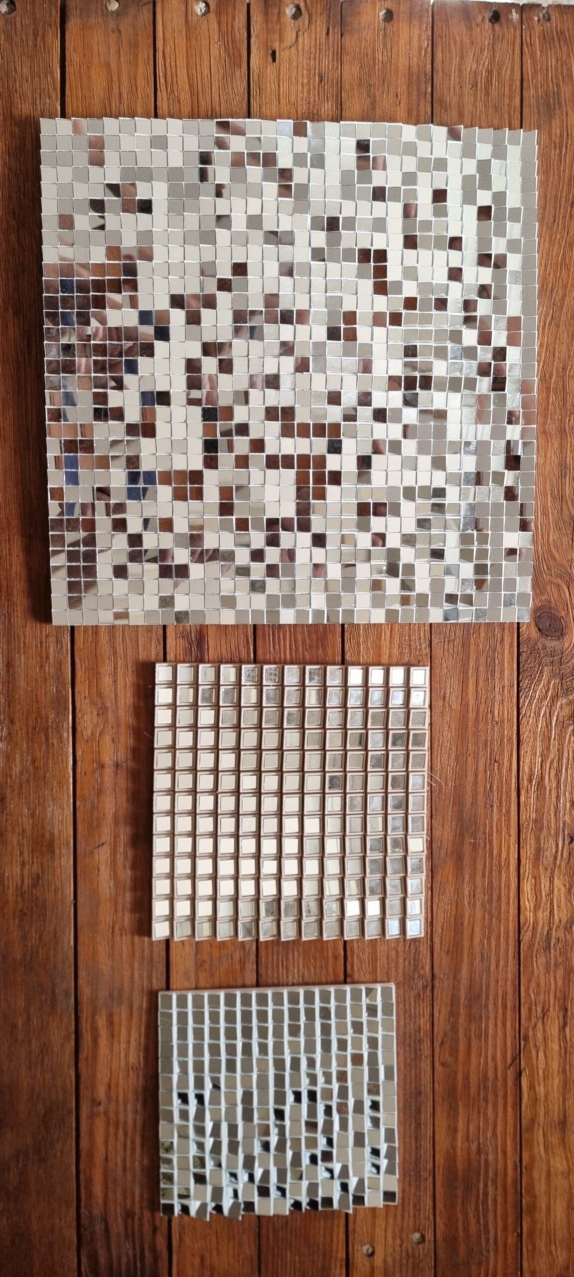
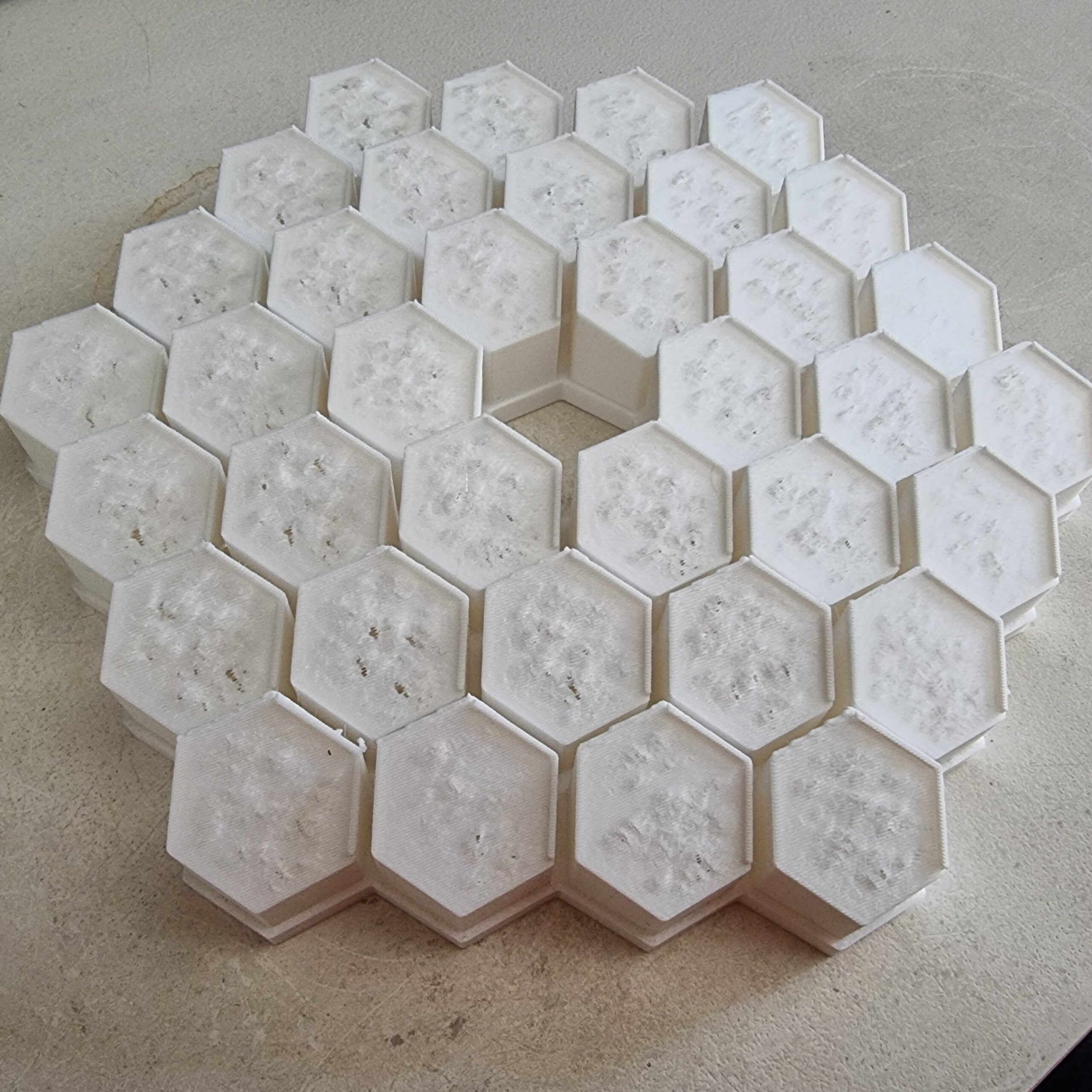
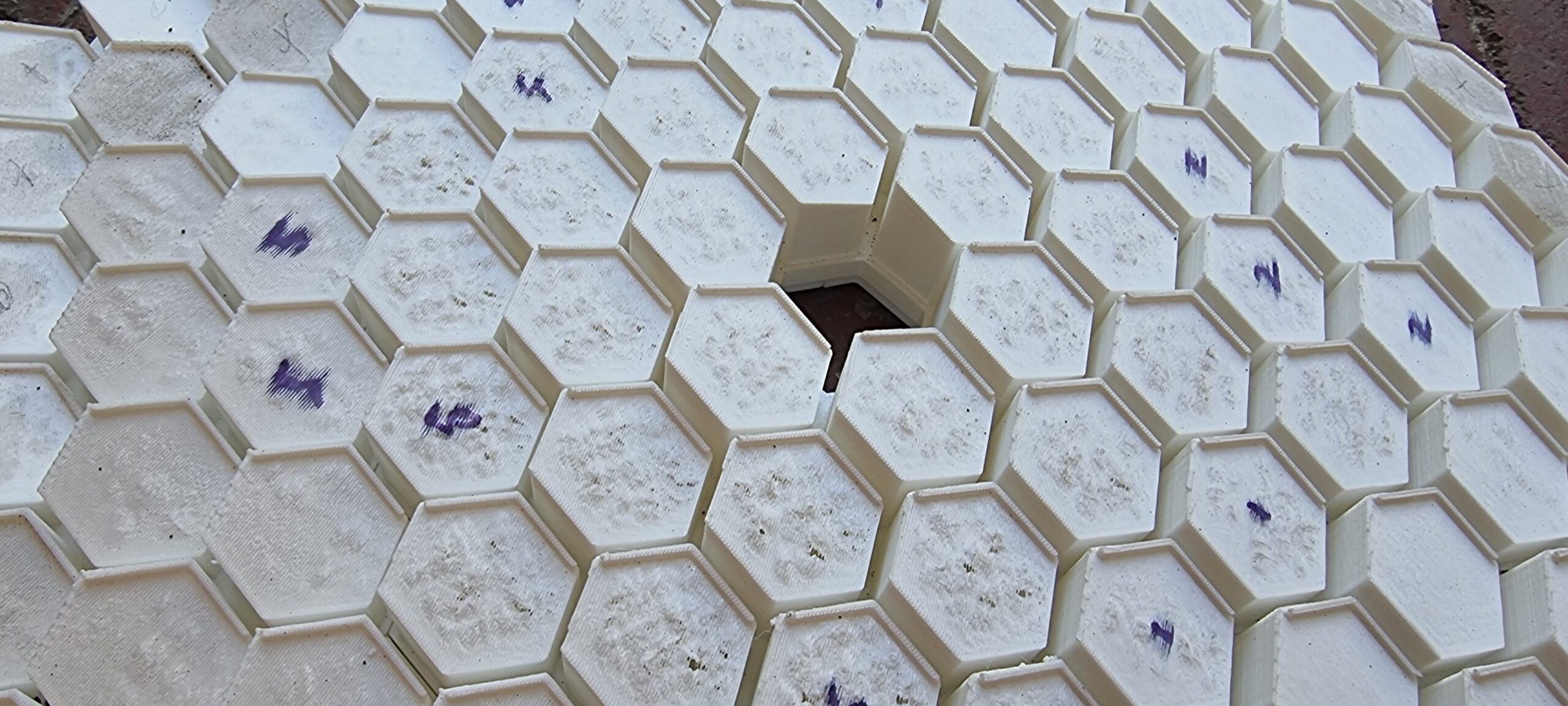
I asked my neighbor to print me a couple of small scale versions of the 3D model generated by the code just to see what would happen if I tried to make it reflective. I tried to make the surface as smooth as possible and asked him to print it with the highest detail possible. When viewing the 3D print with the human eye it actually seems relatively smooth, but if you look closely and spin it three times on the same spot it will still NOT work.
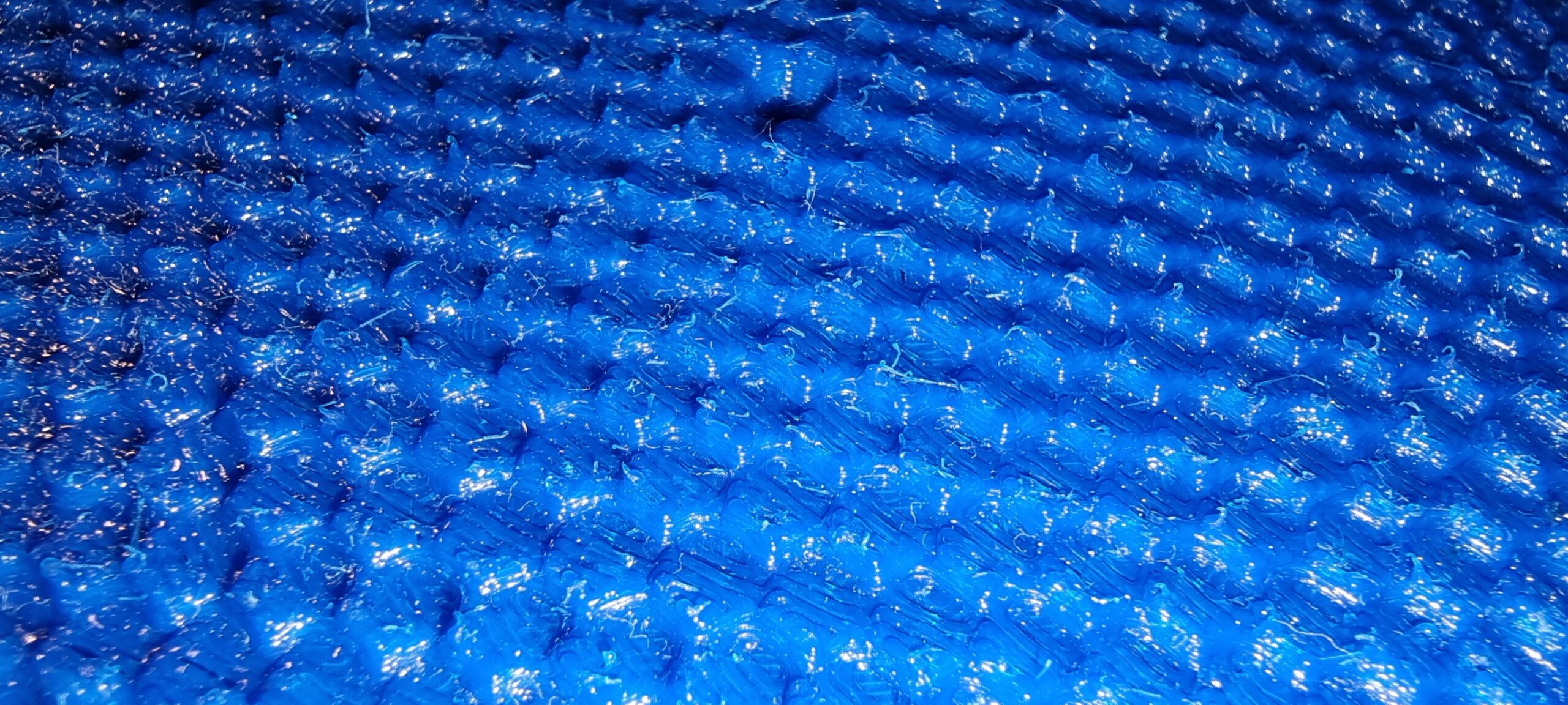
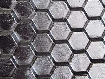
Up close you can see why. Does this look smooth and mirror like to you? Perhaps after a long day’s work and viewed from space it does.
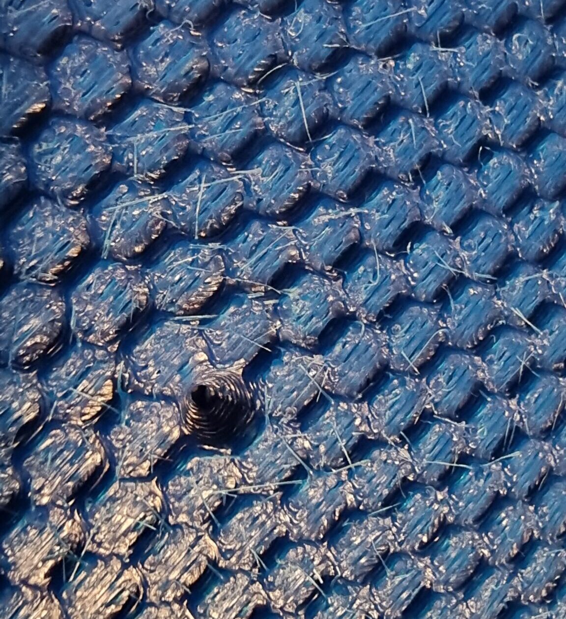
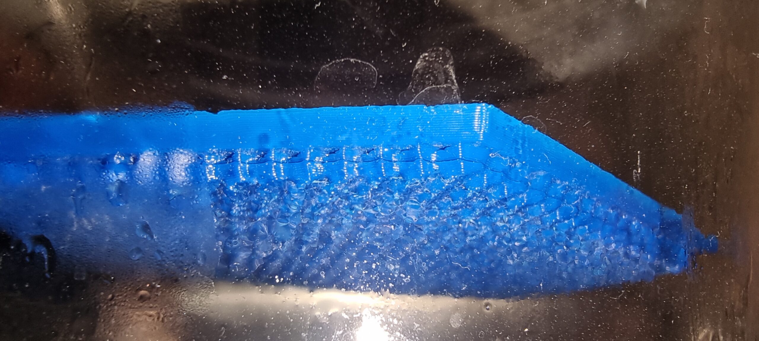
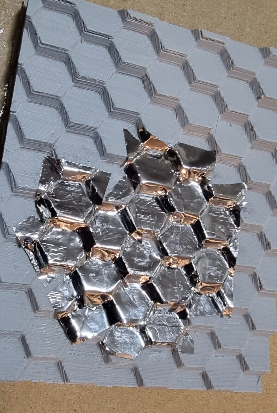
I even tried to do some vapor smoothing on one of the 3d prints. This involves putting the 3d printed part into a big glass bowl (in this case, a flower vase), adding acetone to the bottom, and heating the vase by placing it in hot water. The acetone evaporates and covers the 3d printed parts, then melts the outer layer. Although this helped a bit, I would still not call it a “mirror” finish.
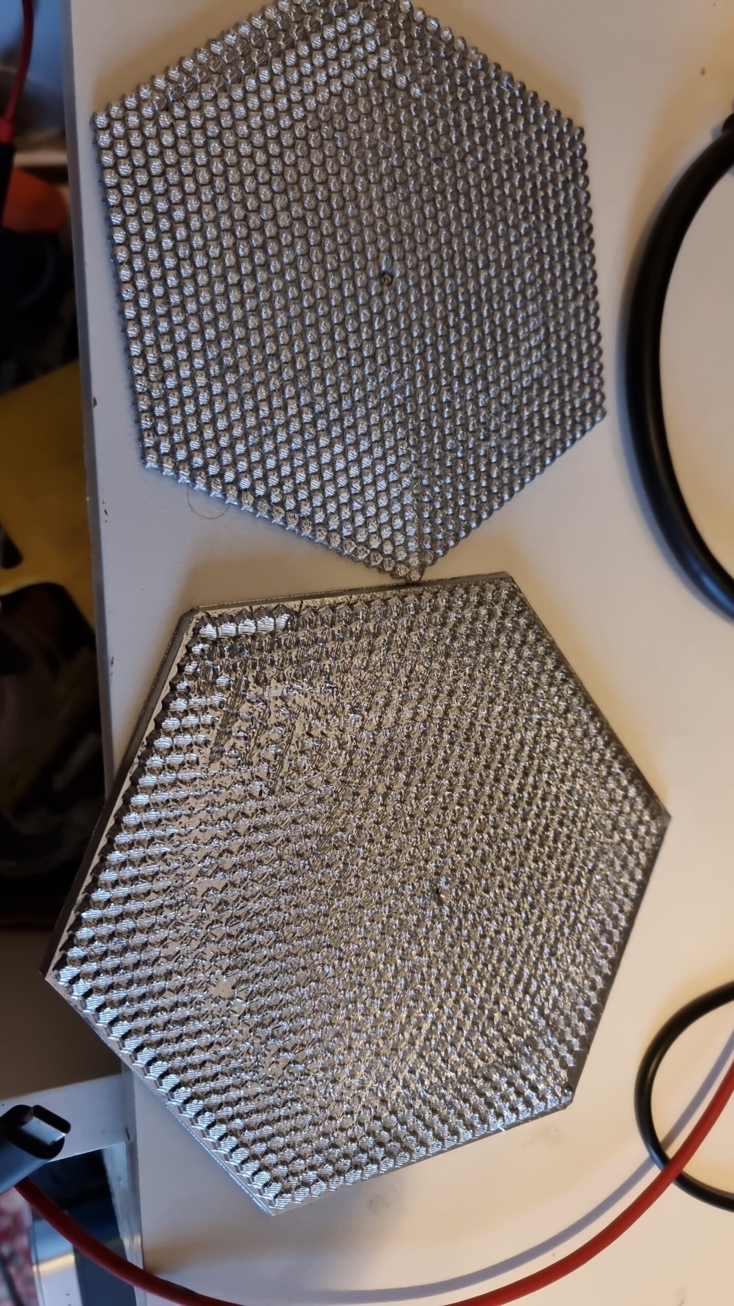
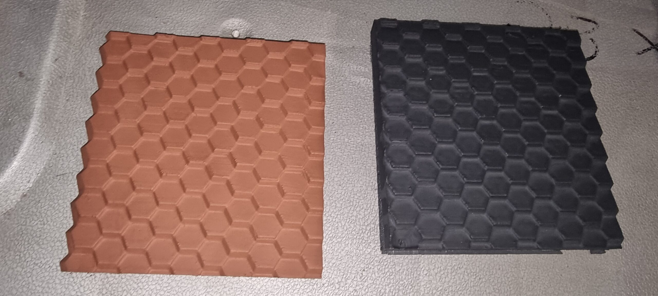
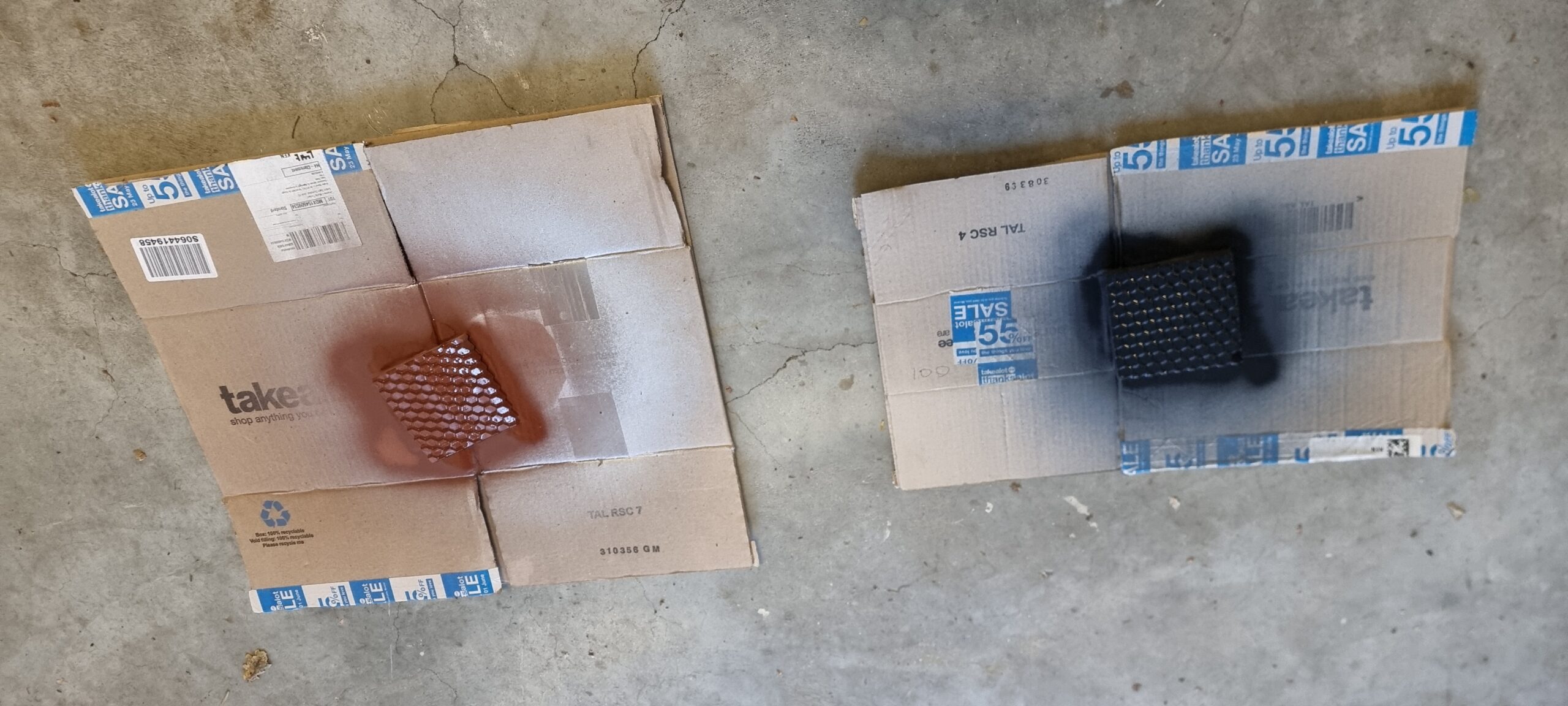
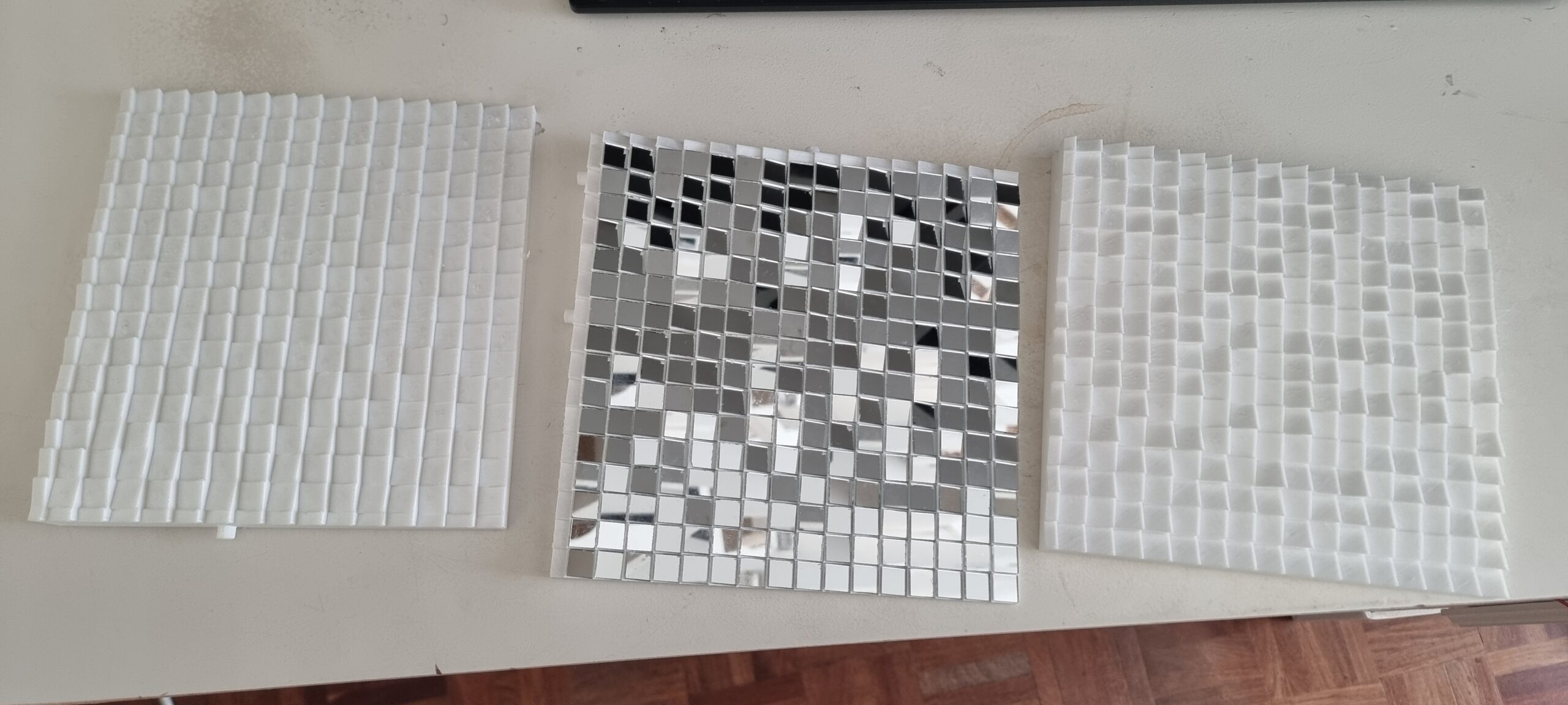
Nevertheless I decided to spray both test prints with the most chromatic spray paint I could find, ending up with what you see below. Silver gray 3D prints. If I were aiming to create some 3D abstract art I would have called it a day right here, but no… Seems this was going to need more playing around than I thought.
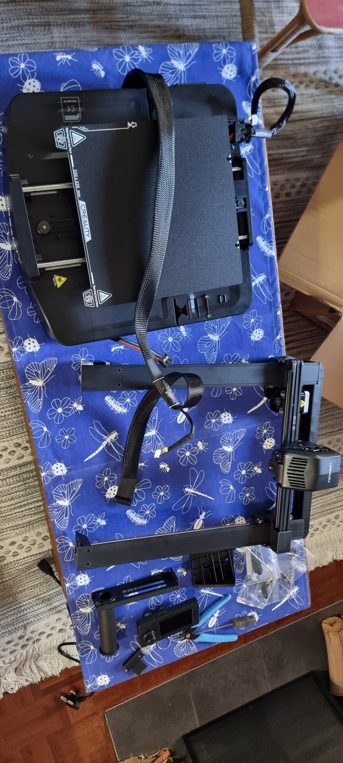
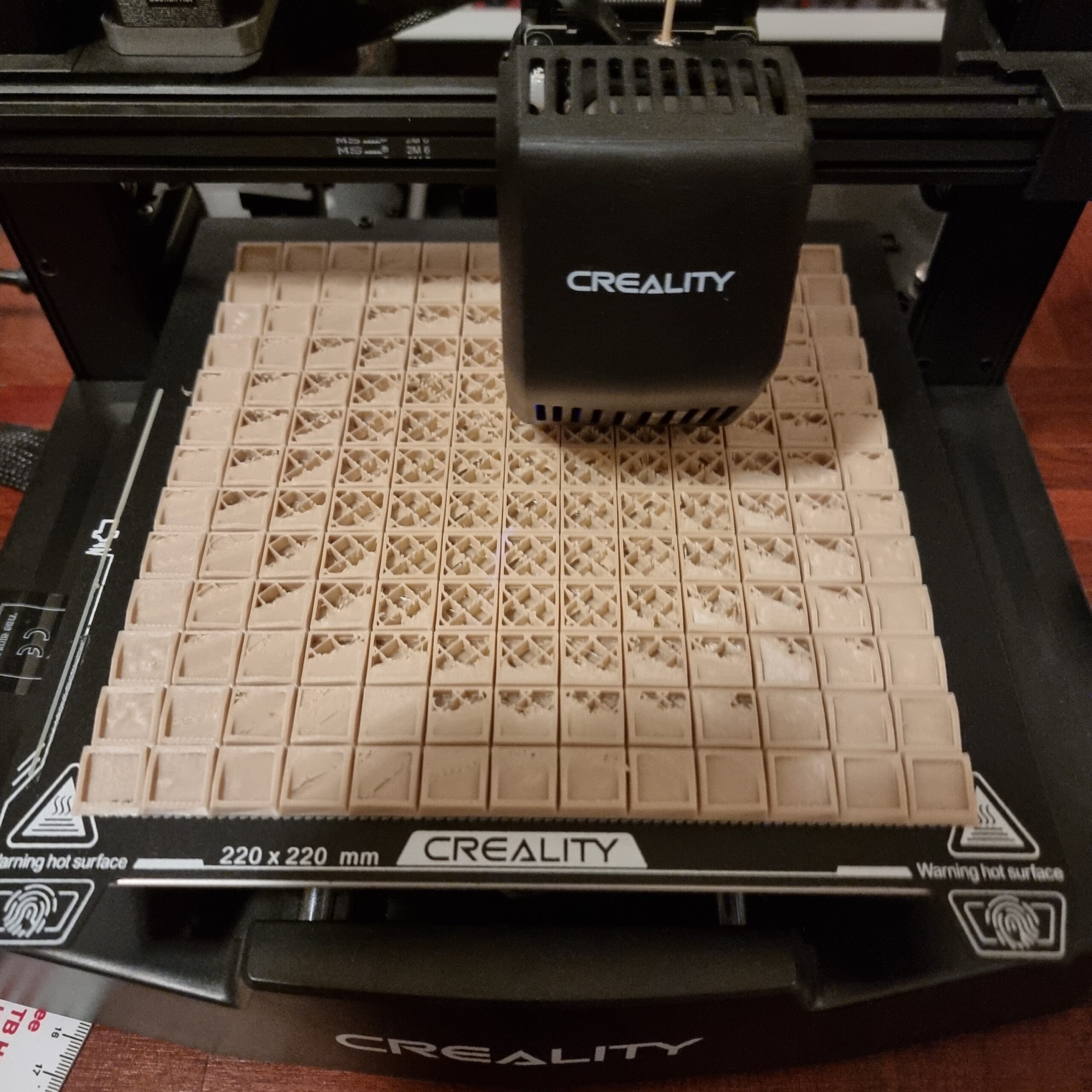
I realized I could not keep on asking my neighbor or colleagues to keep on printing me test samples, so I set out on a research spree to find the best and cheapest printer I could find. I ended up with this bad boy here and spent a weekend setting it up, going ooohhh.. and printing test samples and random things I found on the internet.
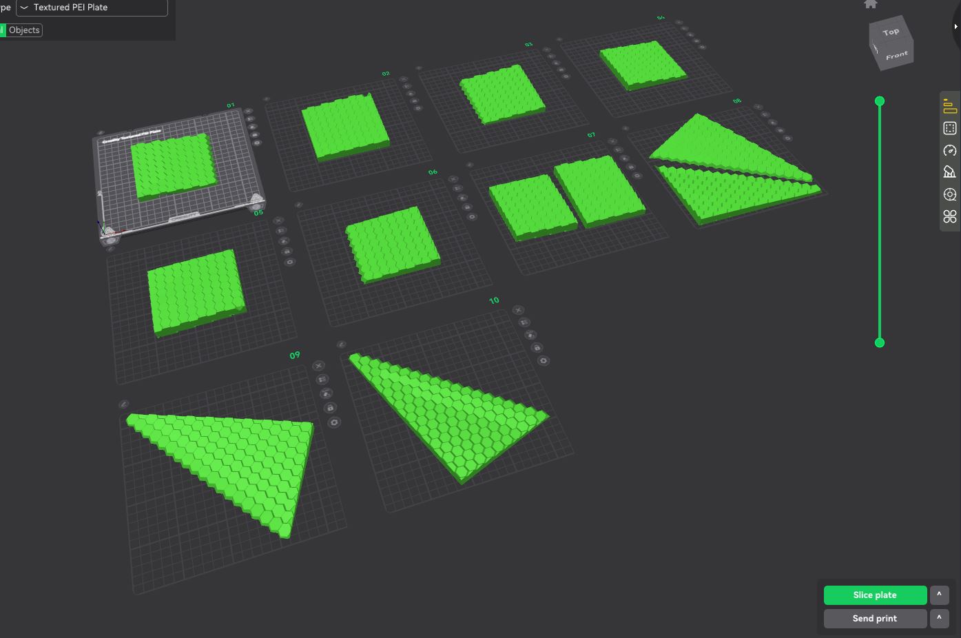
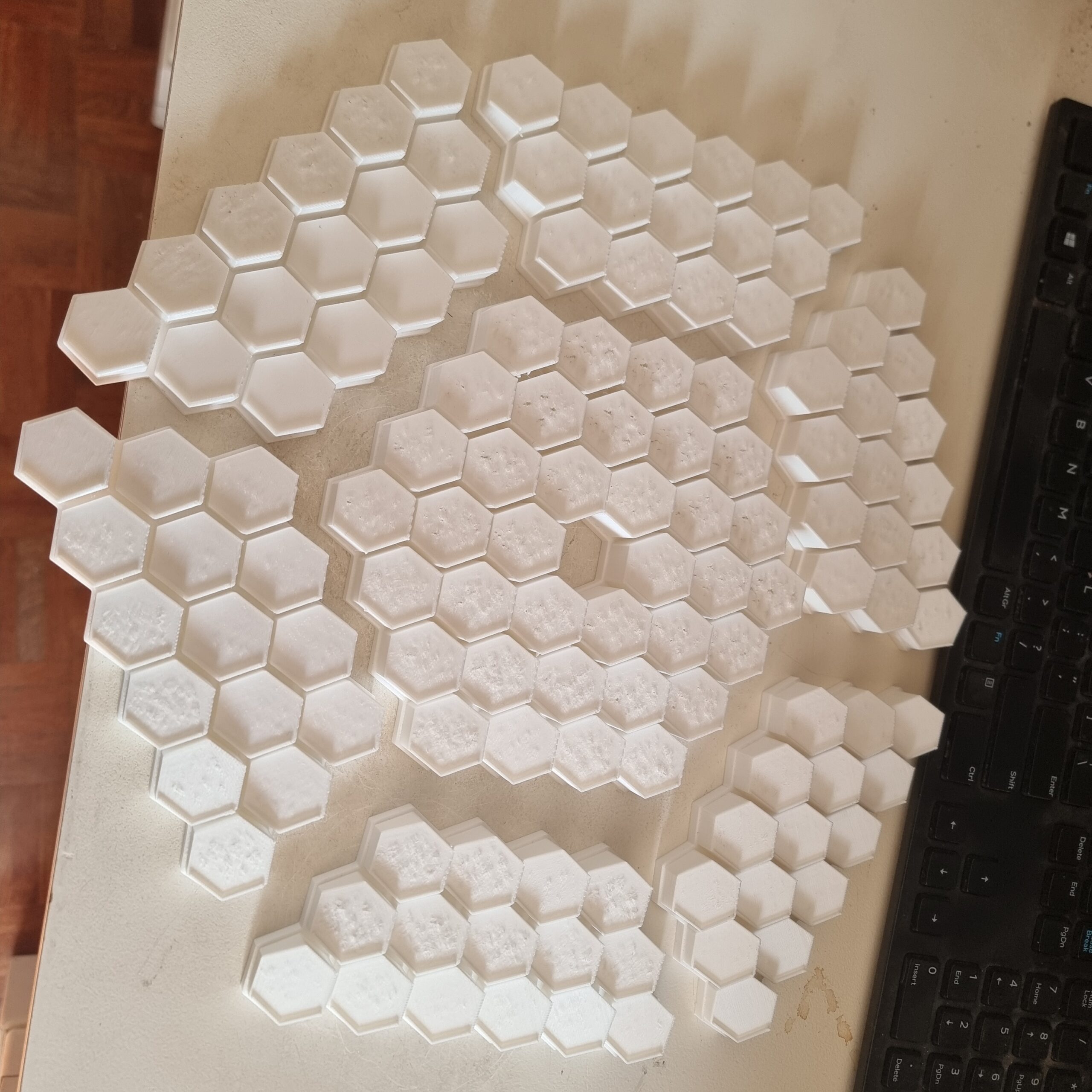
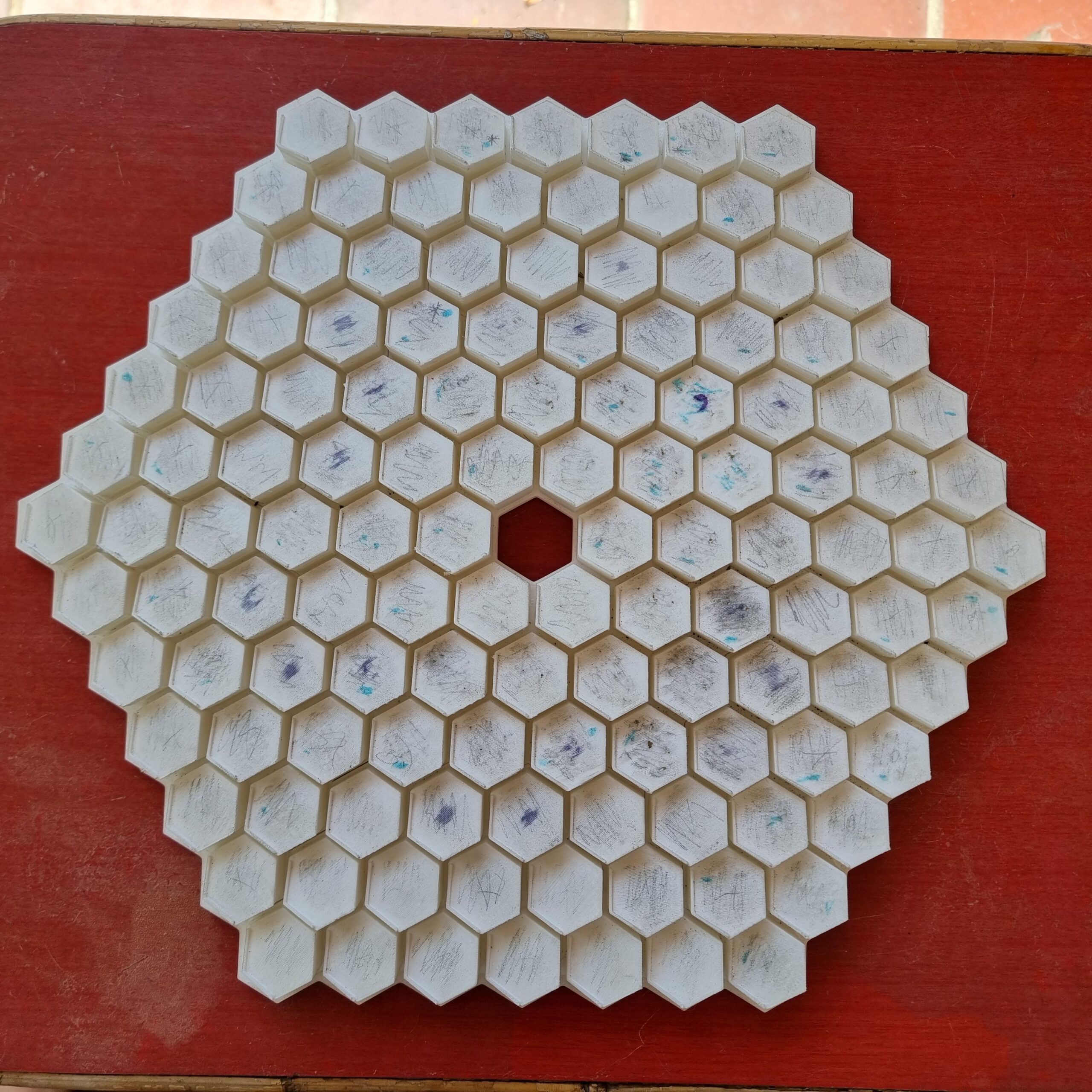
Then, once the novelty wore off, it was back to work. I took the same 3D model I initially had printed small and figured… Well, it just needed a larger surface area to make it even smoother, hence more reflective. So I split up the 3D model into parts and started printing each one… I only ended up printing half of them, as I soon realized this was not the way to go, but I’m getting ahead of myself here. Let past idiot me carry on.
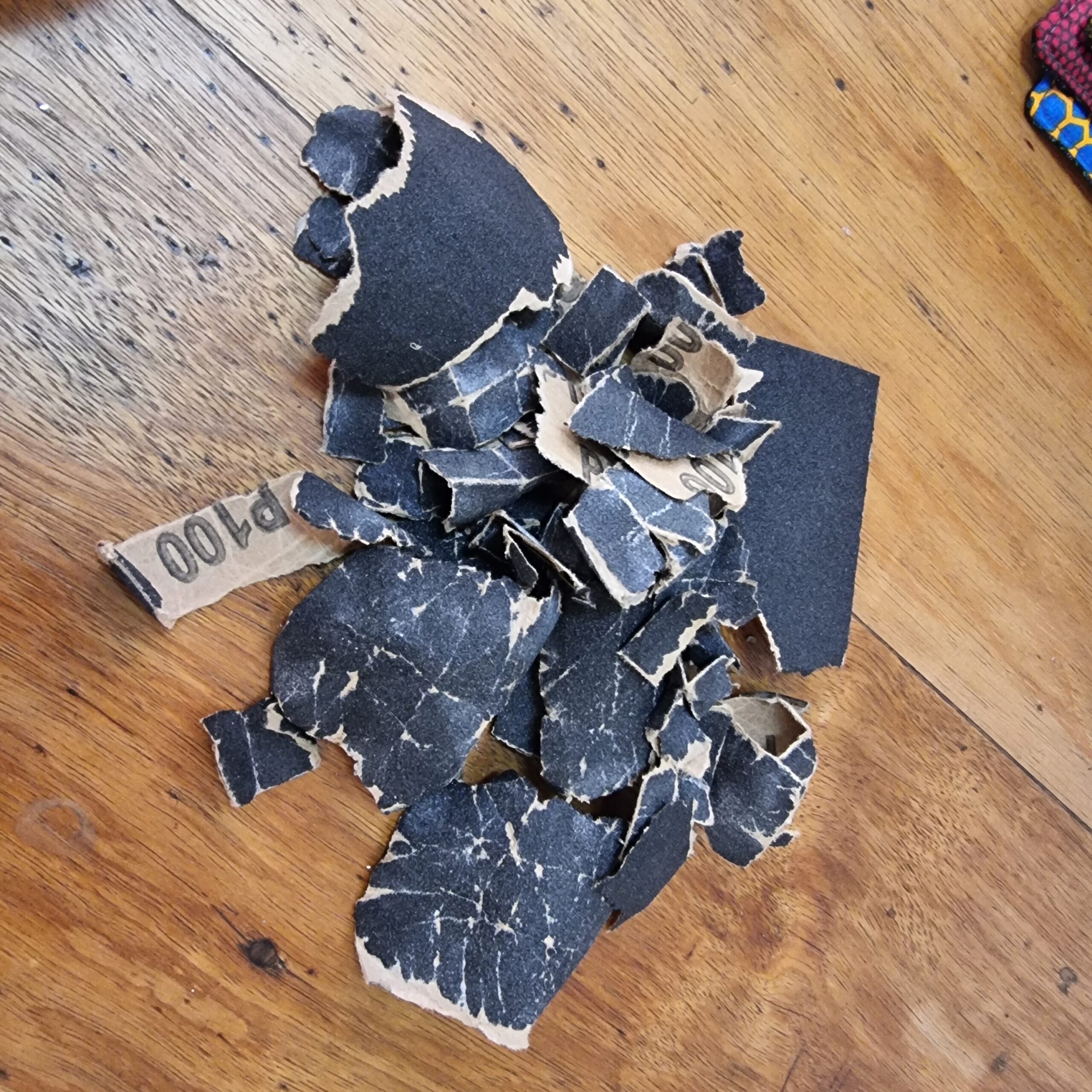
I figured if I spray it with filler spray paint and then sand it still it’s holy (aka sand the hell out of it), it would be shiny enough to reflect light like a mirror. I watched way too many YouTube tutorial videos on how to smooth your 3D prints to a mirror finish that I thought it would be easy. Well, it turns out there is a big difference between a 3D print with a flat surface and this hexagonal monstrosity you see below. I even bought a little mini sander from Temu (yes, I know it was dumb to expect it would work) to speed up the process. It looked more like an electric toothbrush that could not even sand glass.
I sanded (by hand) a couple of test parts over the course of a few days. Yes, I even bought a set of sandpaper with varying grit sizes like they did in the YouTube tutorials. It seems I again only achieved a slightly shiny gray look and I couldn’t even see my reflection, let alone reflect light to make a picture from a distance away.
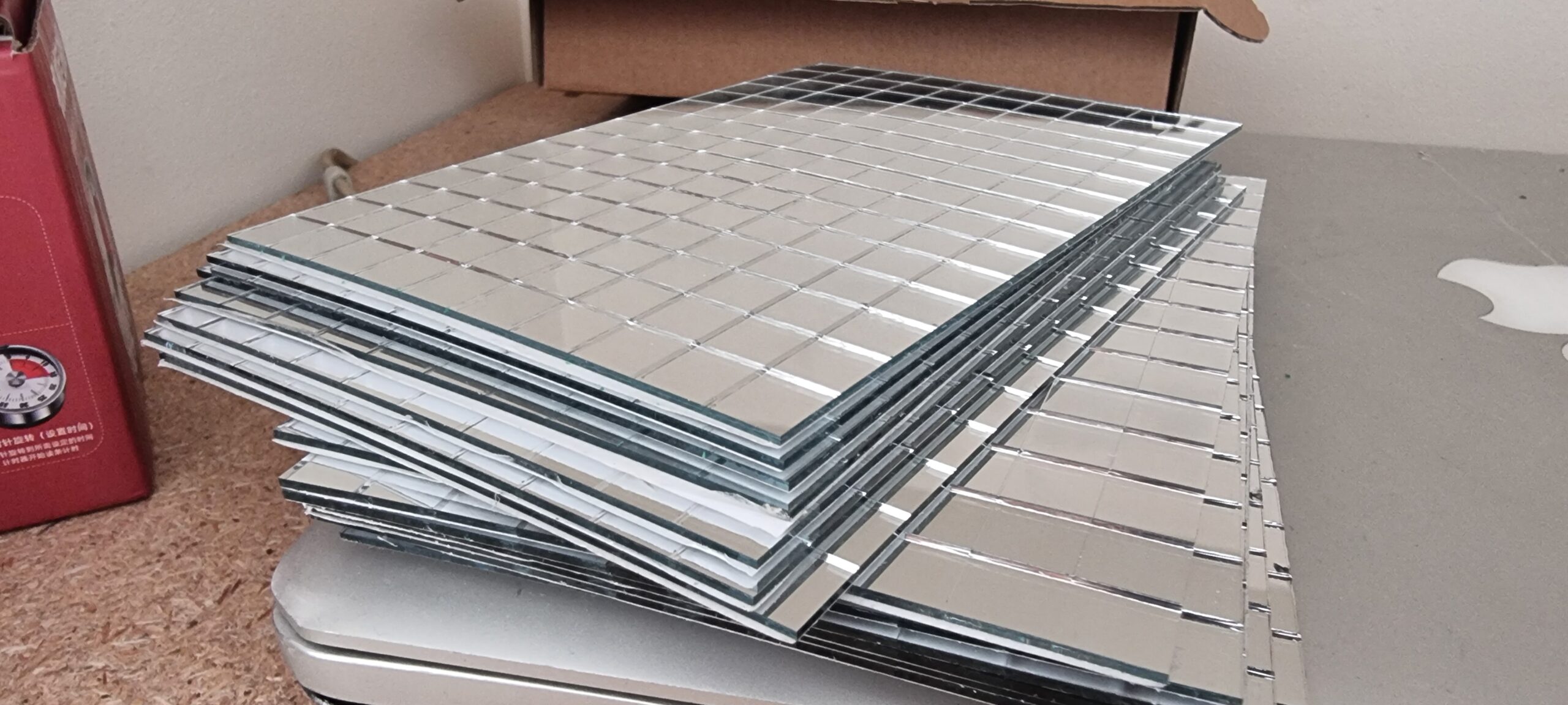
Next I ordered some chrome sticker paper that was really reflective when you get the roll and you dare to have a sliver of hope this project will actually succeed. Yes I know Ben’s original design used mirrors, however the only place he listed was on Amazon and they were a tad (a lot) expensive after all the shipping to South Africa. So I wanted to try something else, especially since I wanted to make a HUGE version of this… See above me not being in touch with reality.
Well after spending an entire movie and some friends’ episodes to meticulously cut the “chrome” stickers and then stick them on a 3D printed test part, I realized a couple of things.
- This is going to take !@##%% ages!
- You still cannot really see yourself or have any decent amount of light reflected.
- You still could see the 3D print lines through the stickers even after spraying and sanding.
- The next morning all the stickers have come loose due to not sticking to the spray paint.
Just also a shout out to my sister for guiding me in the art of finding and applying sticker paper on strange surfaces.
Well, it’s time to try actual mirrors this time. Yes, sometimes I’m slow, but I will get to the same conclusion as Ben did. But being myself, I didn’t know where to get tiny mirrors from. I first spent a week or more finding and emailing all the mirror and water jet cutting companies in South Africa. “Hey, can you cut 1,500 1 × 1 cm tiny mirrors for me please?” followed by the proverbial “Click… hello… are you still there?” response. One company actually responded and said it was possible; however my excitement was short‑lived after being quoted over R8,000 for only 100 tiny mirrors, and I had to find a way to ship them to Johannesburg. So I was stuck for a while. Then my two brain cells ran into each other, and I thought… let’s check Temu. They have all sorts of random stuff (I didn’t say “stuff,” but you get the idea), and to my surprise they had all shapes and sizes of mirrors, including a ton of 1 × 1 cm mirrors used to make things like disco balls. I wasn’t sure if the size descriptions were correct, so I ordered a bunch from a couple of suppliers listed on Temu, and they all arrived as described, leaving me with way more tiny mirrors than I needed. I initially was looking for tiny hexagonal mirrors like in the original design, but that was impossible to get in the size I wanted. So square mirrors it is!
Great, however, now we have one more problem. Ben’s original design was not square, and I now have a ton of tiny square mirrors. So there is only one thing to do.
I (and by “I” I mean me and Claude/GPT doing the heavy lifting) made a minor overhaul of the original code to now represent each mirror as a square instead of a hexagonal section. I also realized after going through the code that there were a couple of settings one can play with, which were set in various places in the code. Keep in mind that at this stage I moved all the code from a notebook to a plain Python script so I had everything in one place to mess around with. I first added all the variables I wanted to play with at the top of the script, ran the script, generated a 3D model, changed something again, and reran the script. That got old very quickly, so I created an interactive little program where the 3D model was displayed and all the parameters were sliders that you can tweak, and the 3D model would update in real time. I also added a cache so that if I did not change the reference image it would remember the coordinates and load the program much faster instead of recalculating or dimensionally reducing the coordinates to the number I set beforehand.
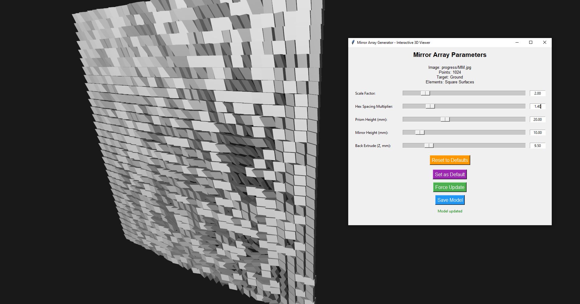
With this, I was able to tweak things like the spacing, the size of the projected image, and the thickness of the 3D model. Once done, I simply had to press “Save Model” and the 3D model was saved and ready for testing. This sped up my workflow a lot, and I managed to generate many variations to learn what the best settings would be.
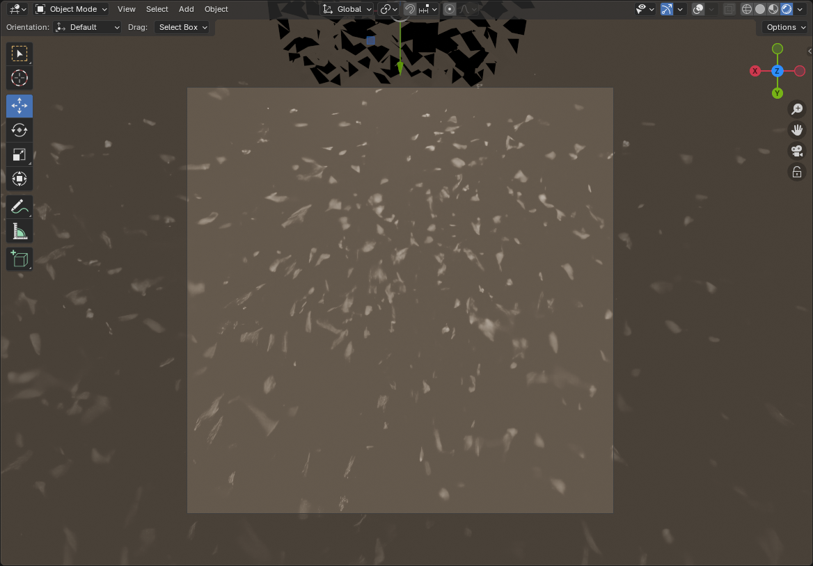
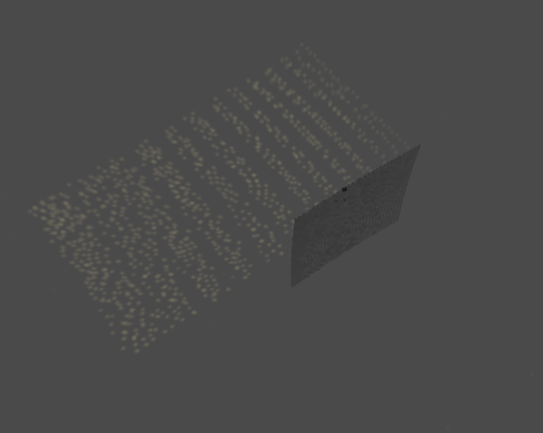
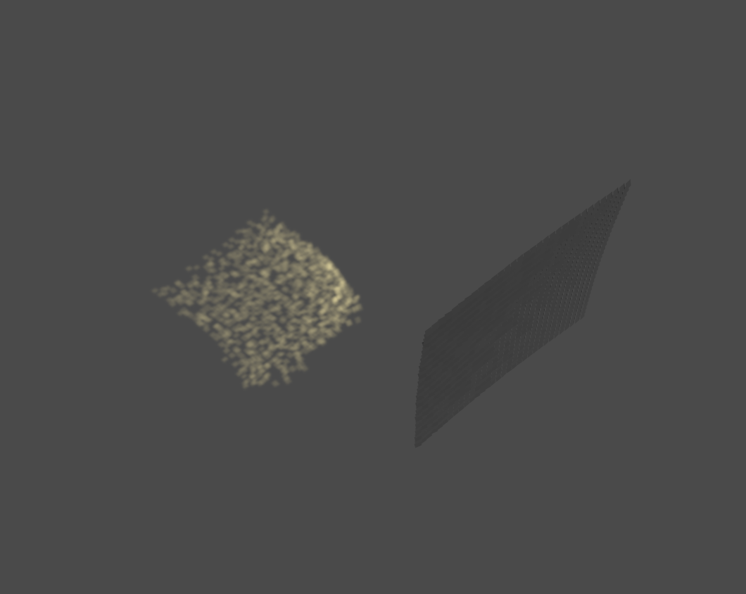
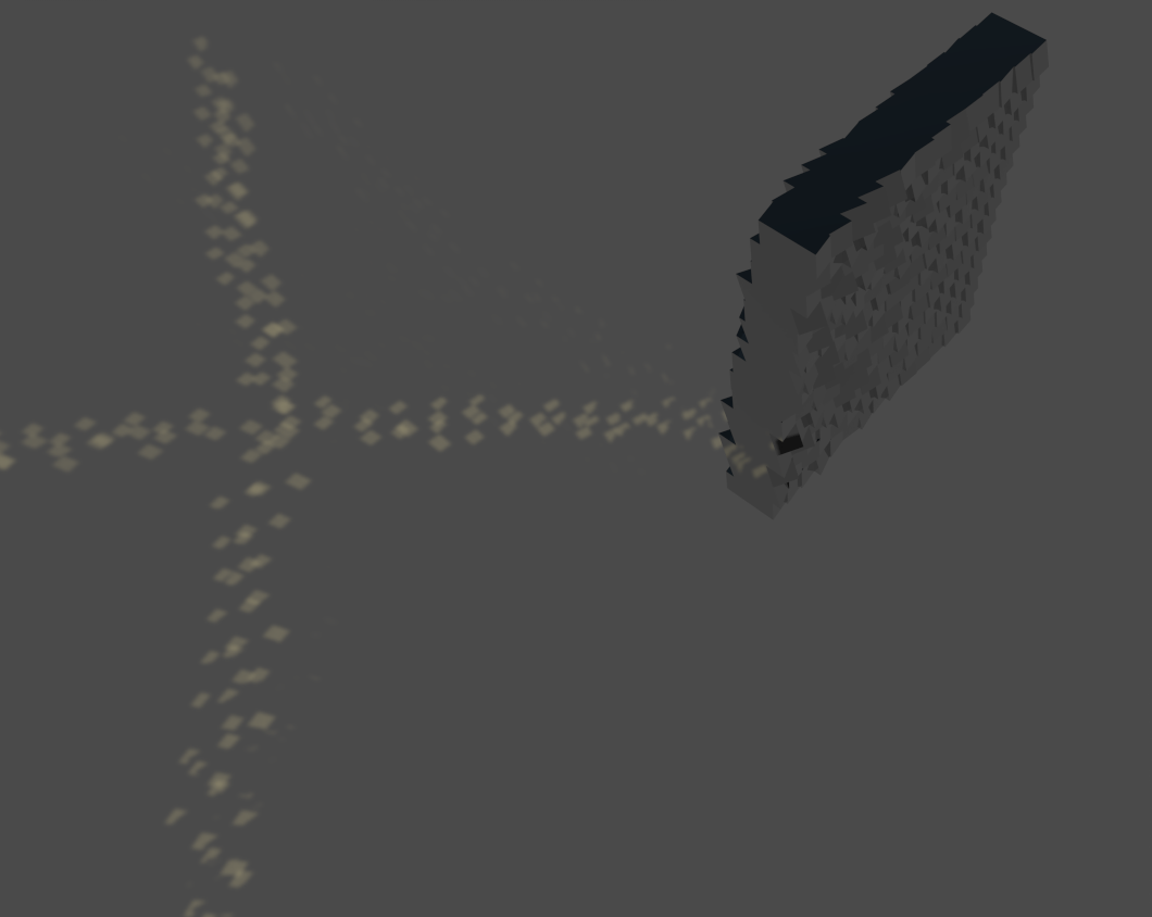
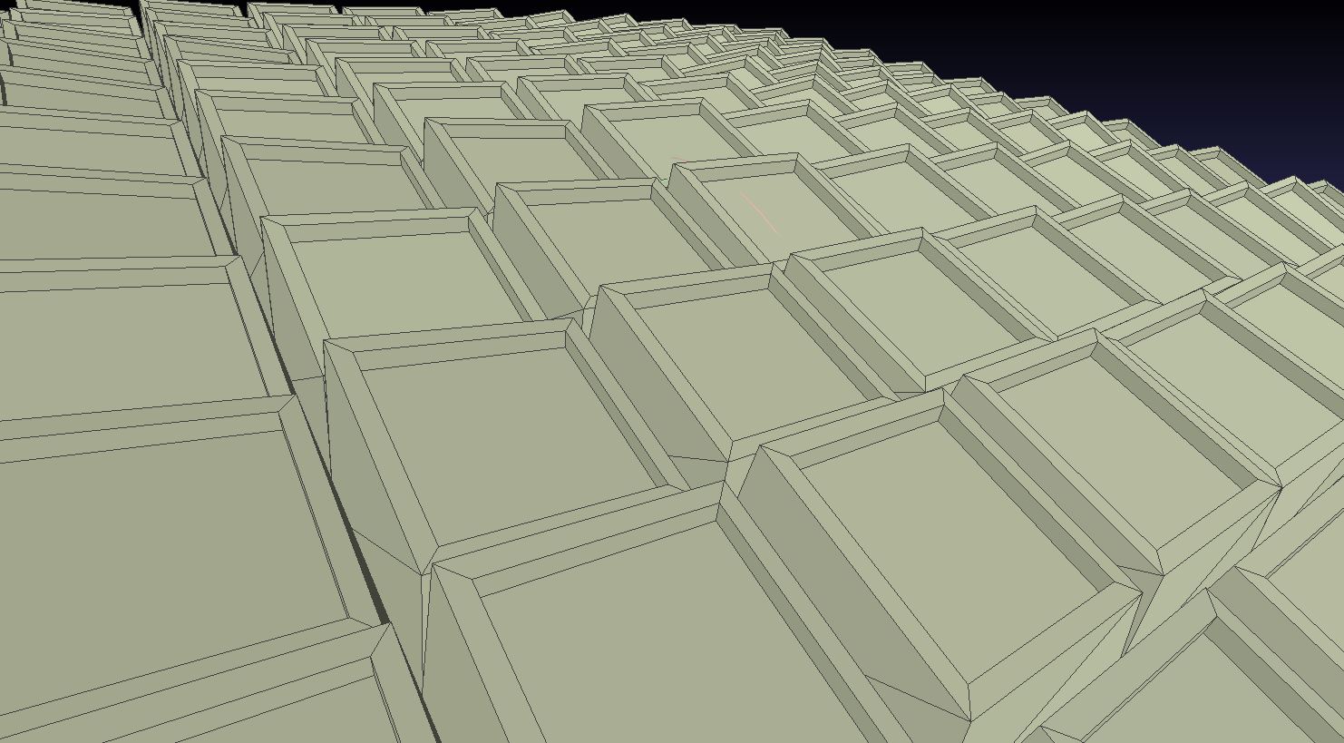
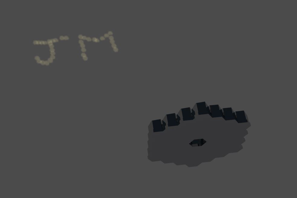
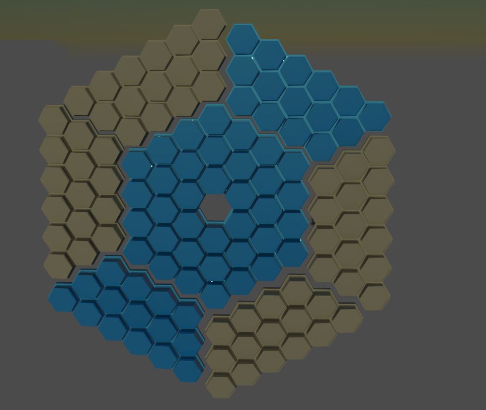
Below is one of the 3D models generated in such a manner. You cannot really make out anything; however, you can see the mirrors are facing in other directions, hinting at something. Also, Ohhh Shiny!
I did a couple of tests to play with the setting I configured above. Some were just to see how detailed I could get the image by creating a “bar code” with lines going from thick to thin. I also had an idea to try and overlap some dots to create a gray scale image with some areas being brighter due to multiple dots being projected in the same place. However, since I had a limit in the number of “pixels” and I would have needed to do a major overall (again) on the base code, I opted to skip this step since I’ve already been busy with this for a couple of months and people started asking if I was perhaps getting a bit too obsessed with this project. Little did they know the rabbit hole will be getting much, much deeper!
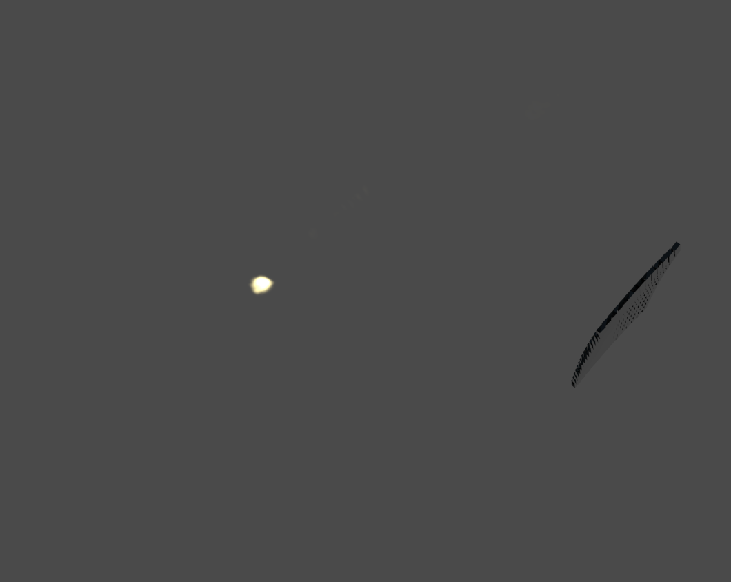
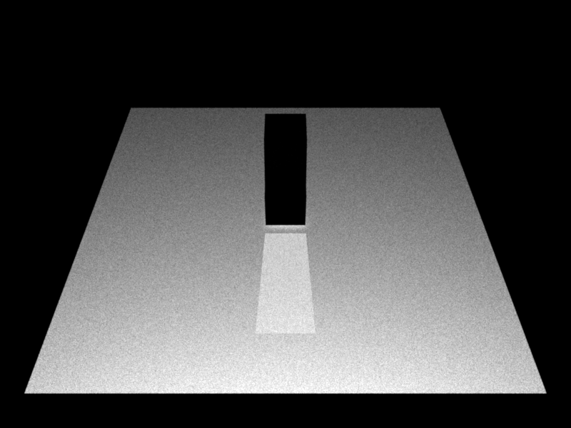
After playing around with various images, I realized I would need to do a physical test at some stage. I wanted to go with the JM2 image at first; however, I wanted something simple and I needed to see how much distortion, etc., a real world object would have. So I decided to just create a simple X. This way I could see if the lines of the X bent in during the projection. It would also give me a good idea how high one would need to hold the 3D printed version in real life for the image to be visible on the ground. So X it was then.
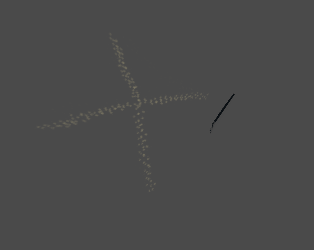
Here is the first virtual test so I could do a comparison with the 3D printed version.
And let the printing begin. I was very excited to see the first version being printed and I did a lot of “3d print TV” watching during the process. Getting the first layer to stick to the bottom print plate was sometimes a bit of an issue. Seems that touching the plate with your hands gets it full of dirty human oil (order now!) and you need to clean the plate with acetone beforehand. Once I found this trick I did not have any more spaghetti monster prints and my use of “French” words decreased dramatically.
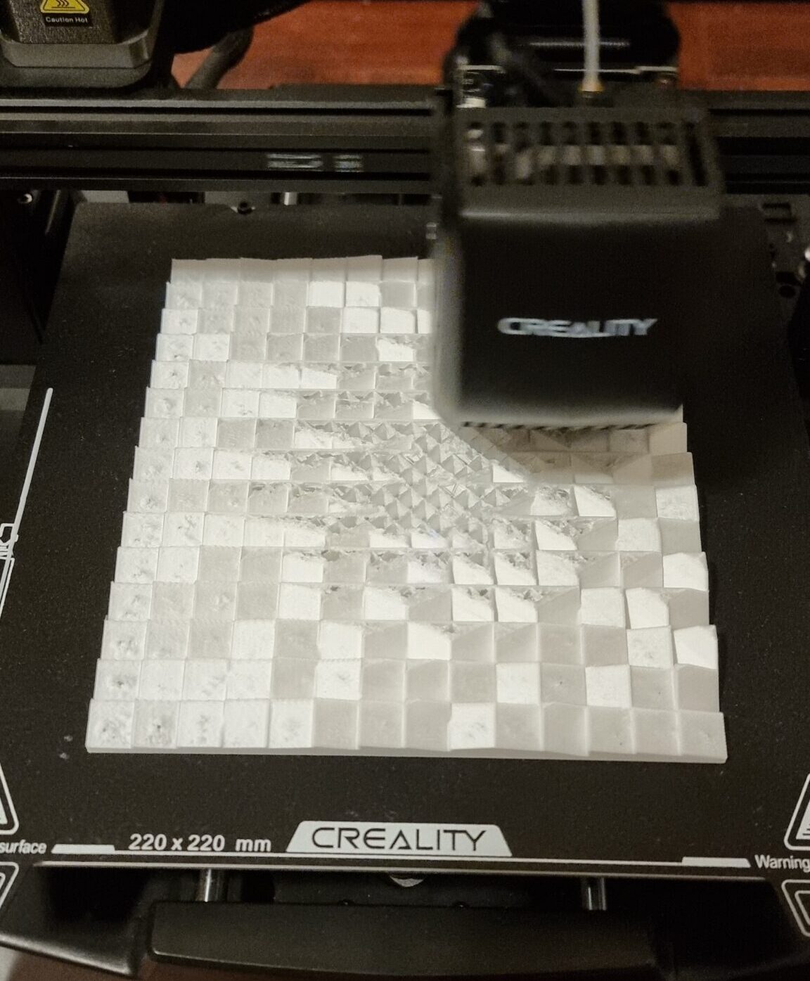
Once printed, it was the “fun” part of sticking the little mirrors on the 3D printed part. Luckily, whoever made these little mirrors was smart enough to put glue on the back so I could just peel and stick. Good idea, but I think it came back to bite me later in this project.
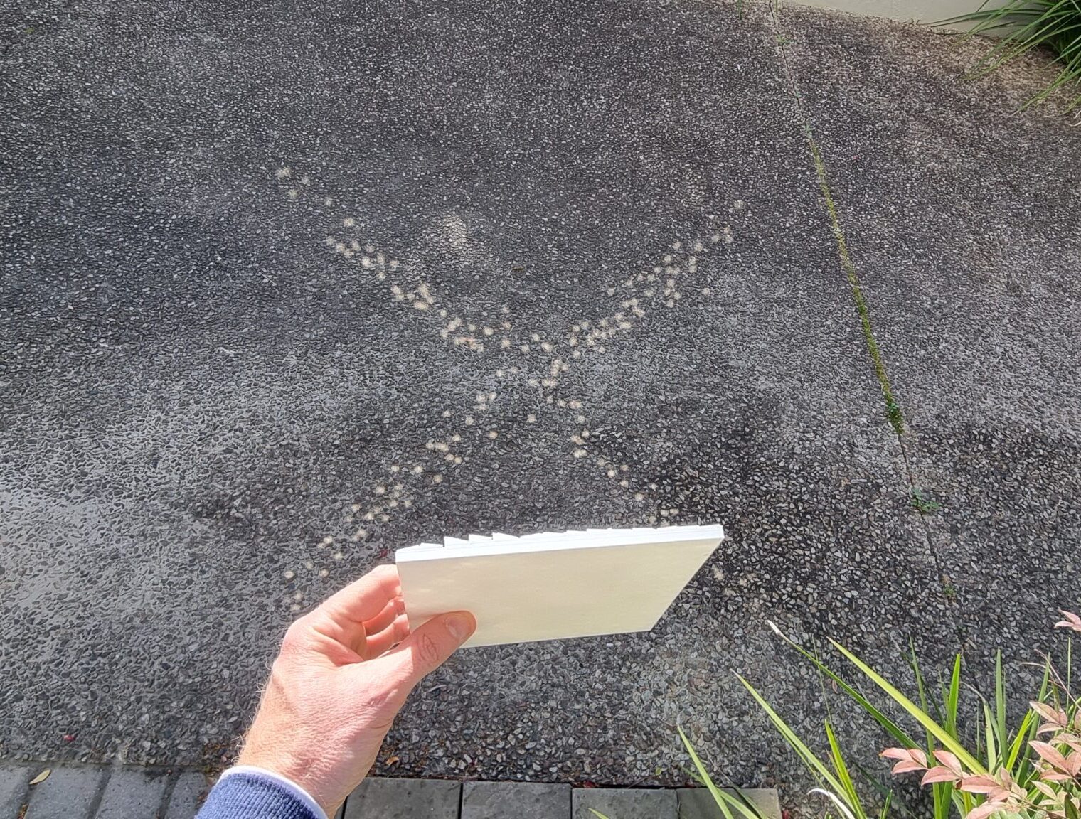
Here you can see my first test after finding the right angle of the sun and a day without clouds. I will tell you I did a little happy dance when I first saw the “X” being projected on the ground. WOW… this is actually going to work. Shame on poor past me with such high hopes.
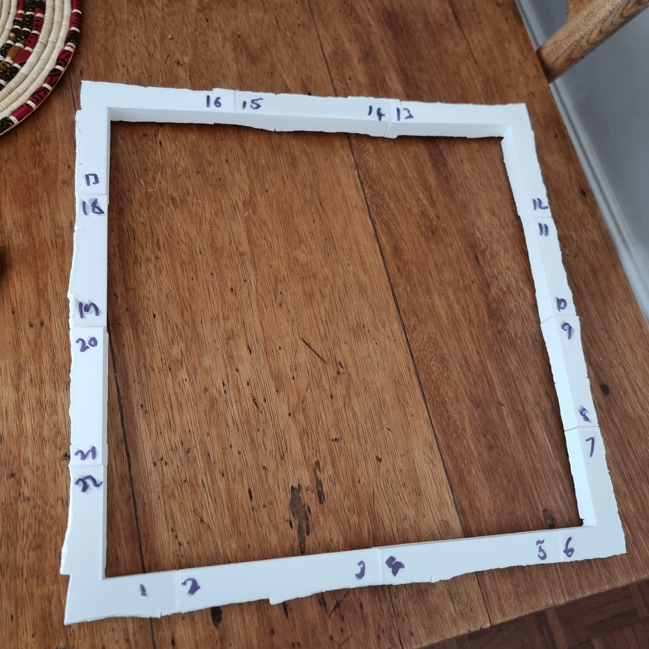
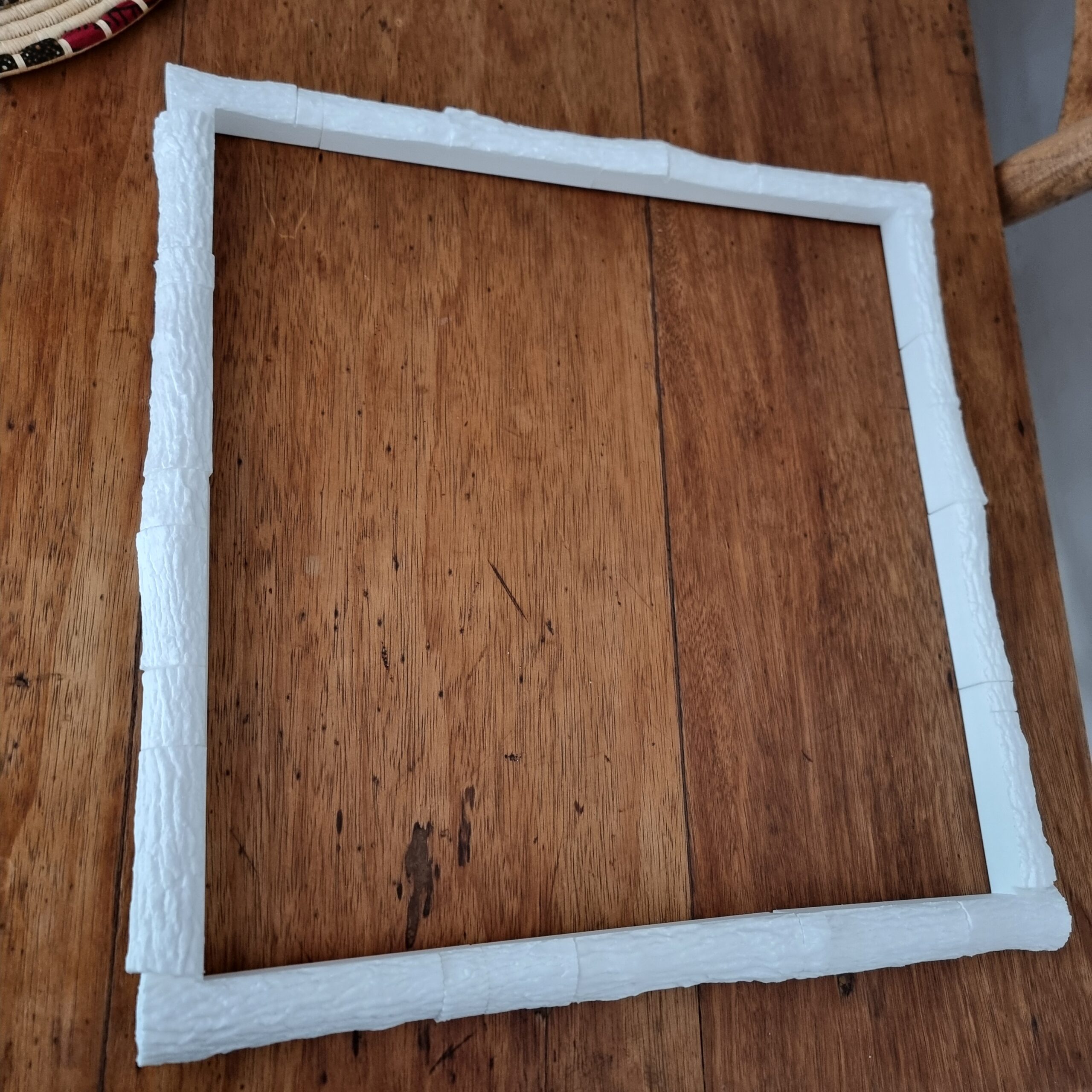
Well the “X” worked, so why would a much more complicated “Marry Me?” not work. Right… Let’s go full scale. No more need to test! Hooray! So I spent the next couple of weeks designing the “final” version that is four times bigger. Even with a wood themed border and everything! I mean why would it not work.
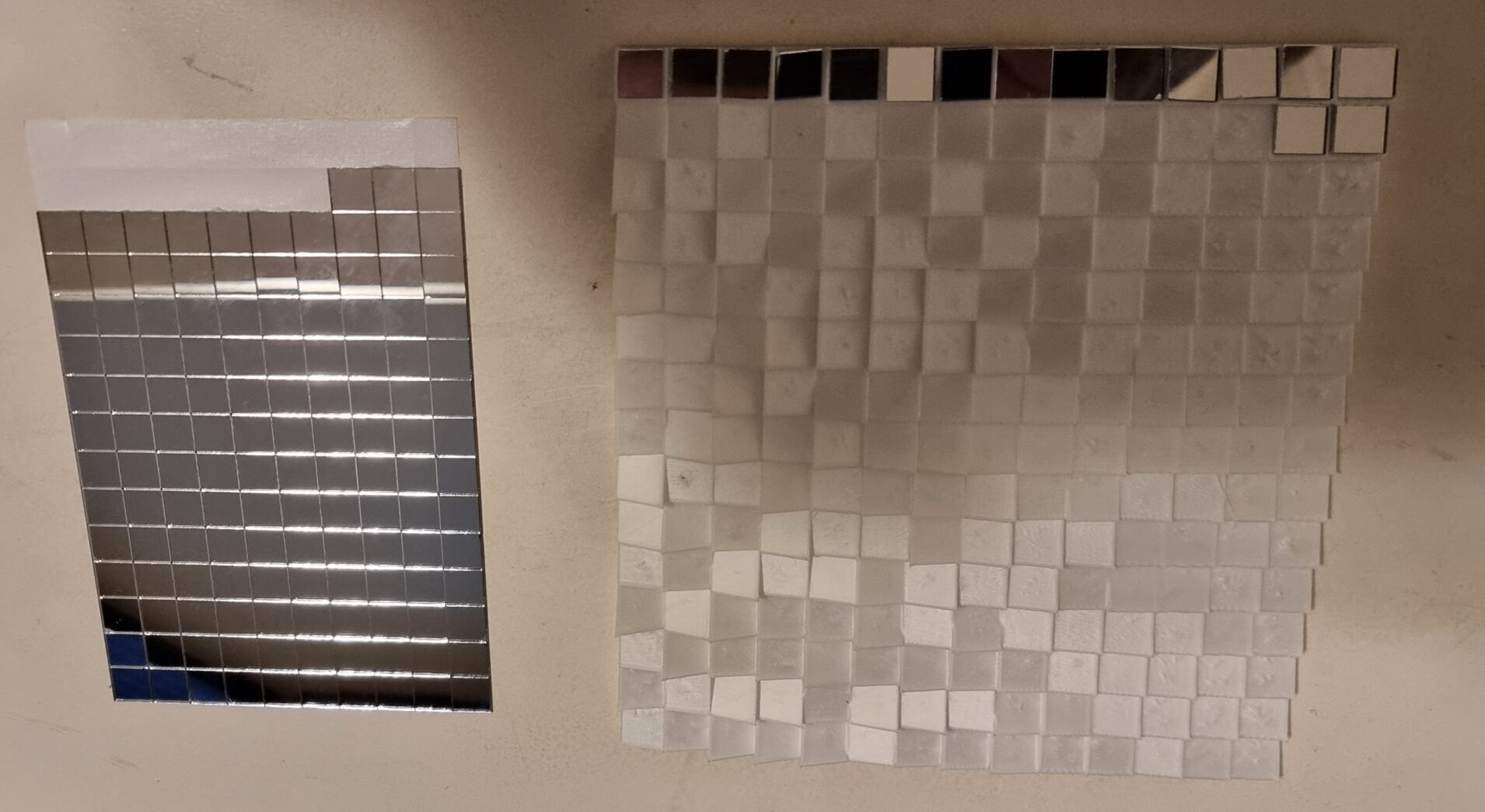
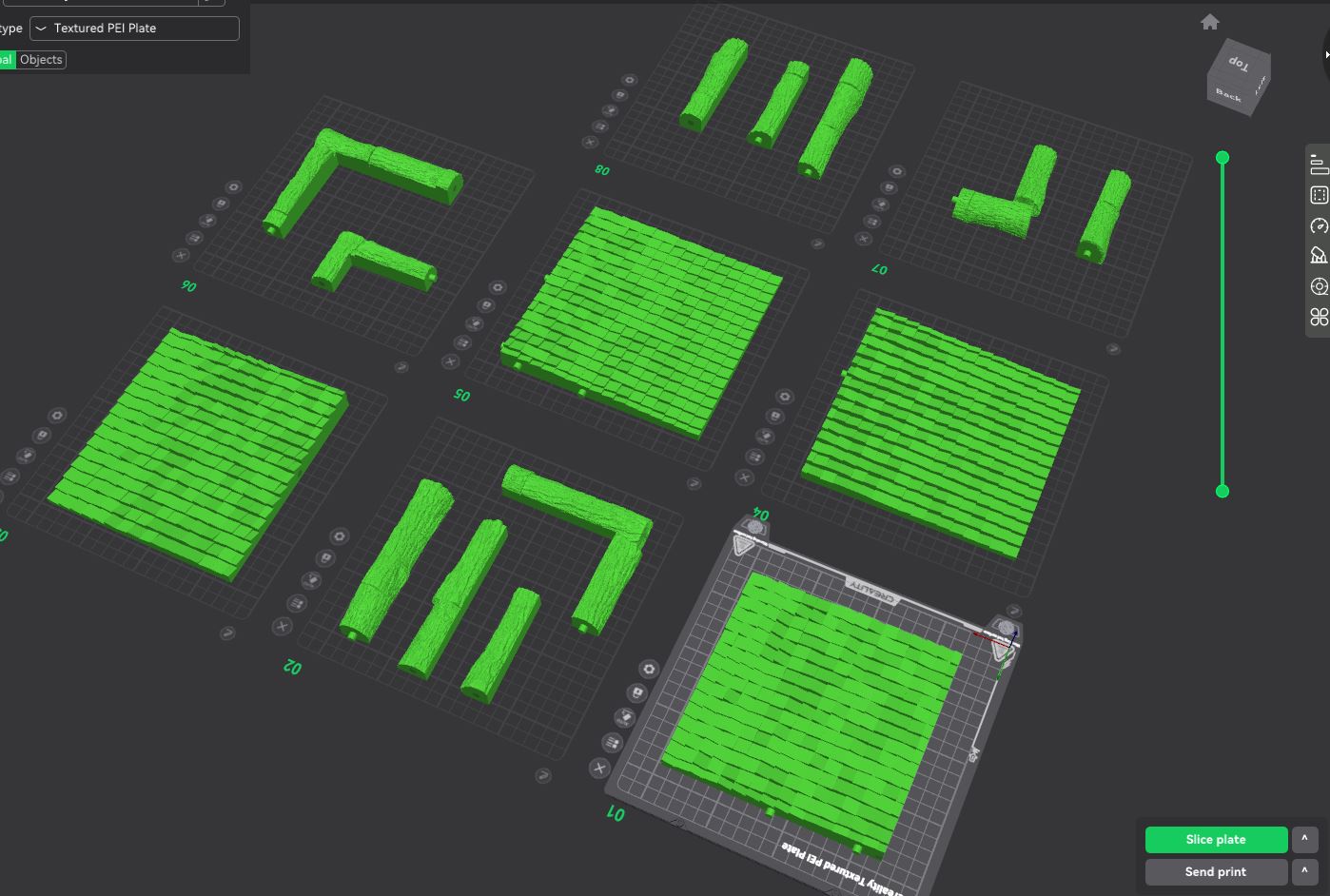
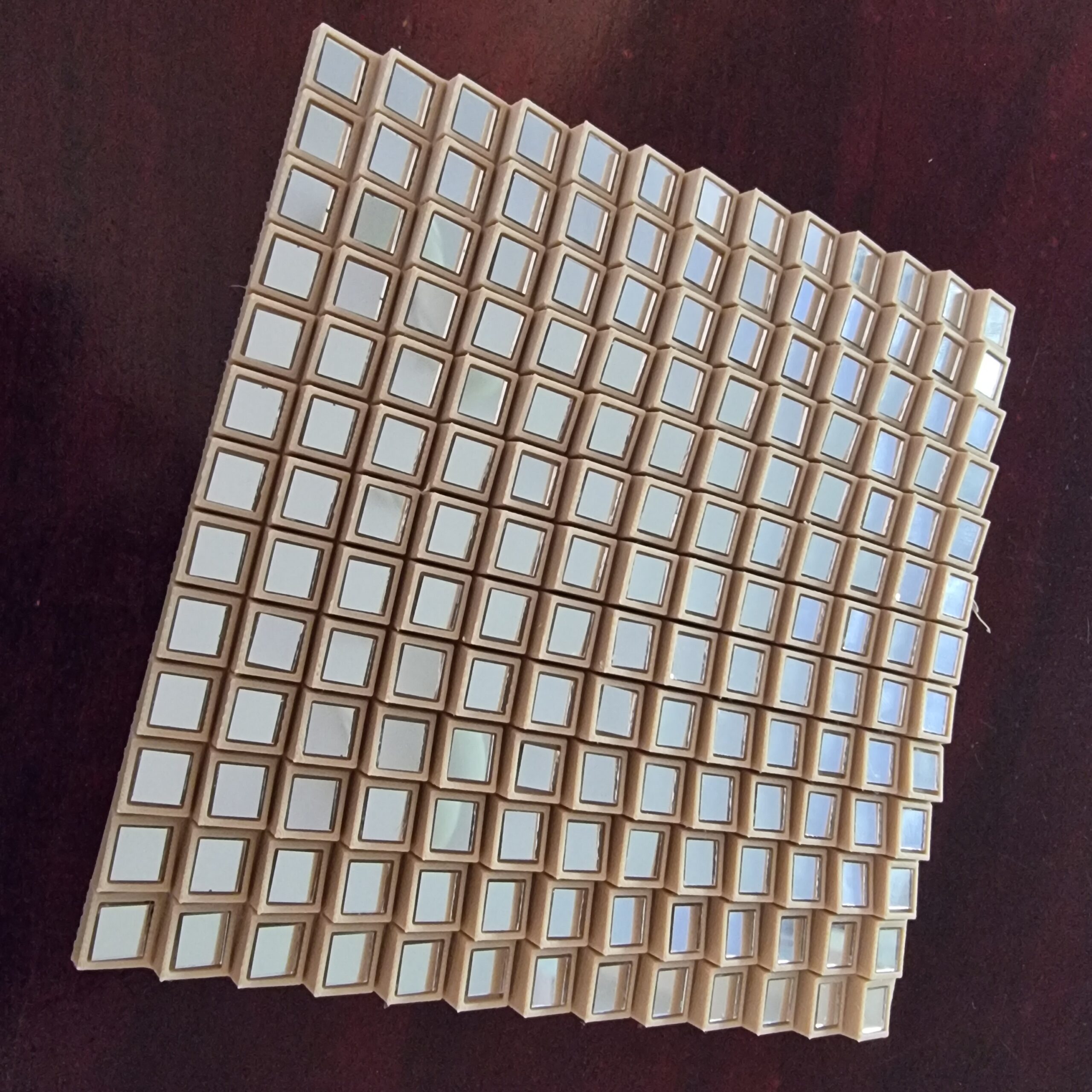
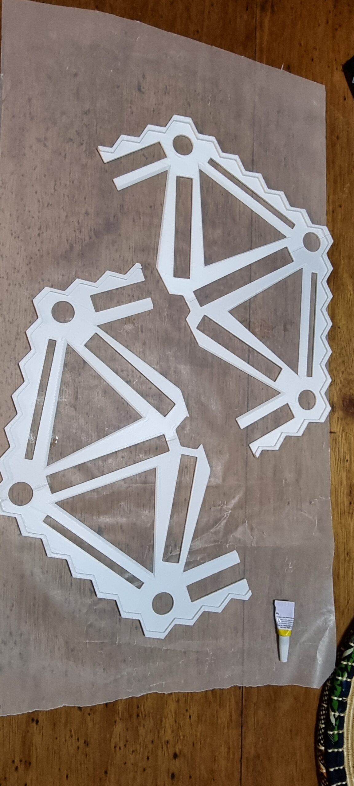
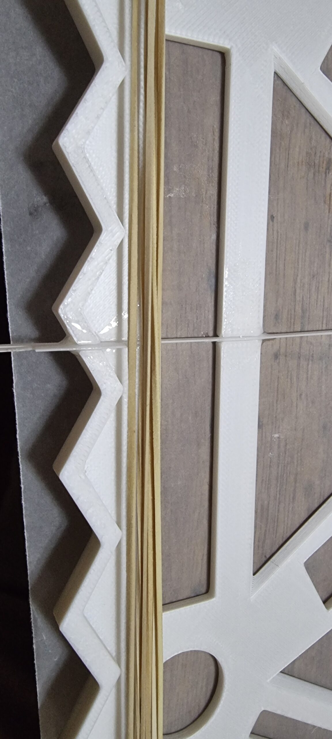
Here are the final parts I cut into sections so they would fit on my 3D printer. I even added little guides so the parts could fit snugly. It looks pretty cool just as this. Taking into account how much work I put into this version alone.
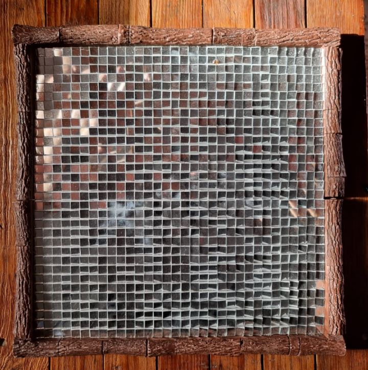
Well, with all the parts printed, it was onto sticking all 1,024 tiny mirrors and assembling the border. I will tell you now, I never want to see a tiny little mirror again in my life! And if anyone wants the leftover mirrors, you are welcome to it!
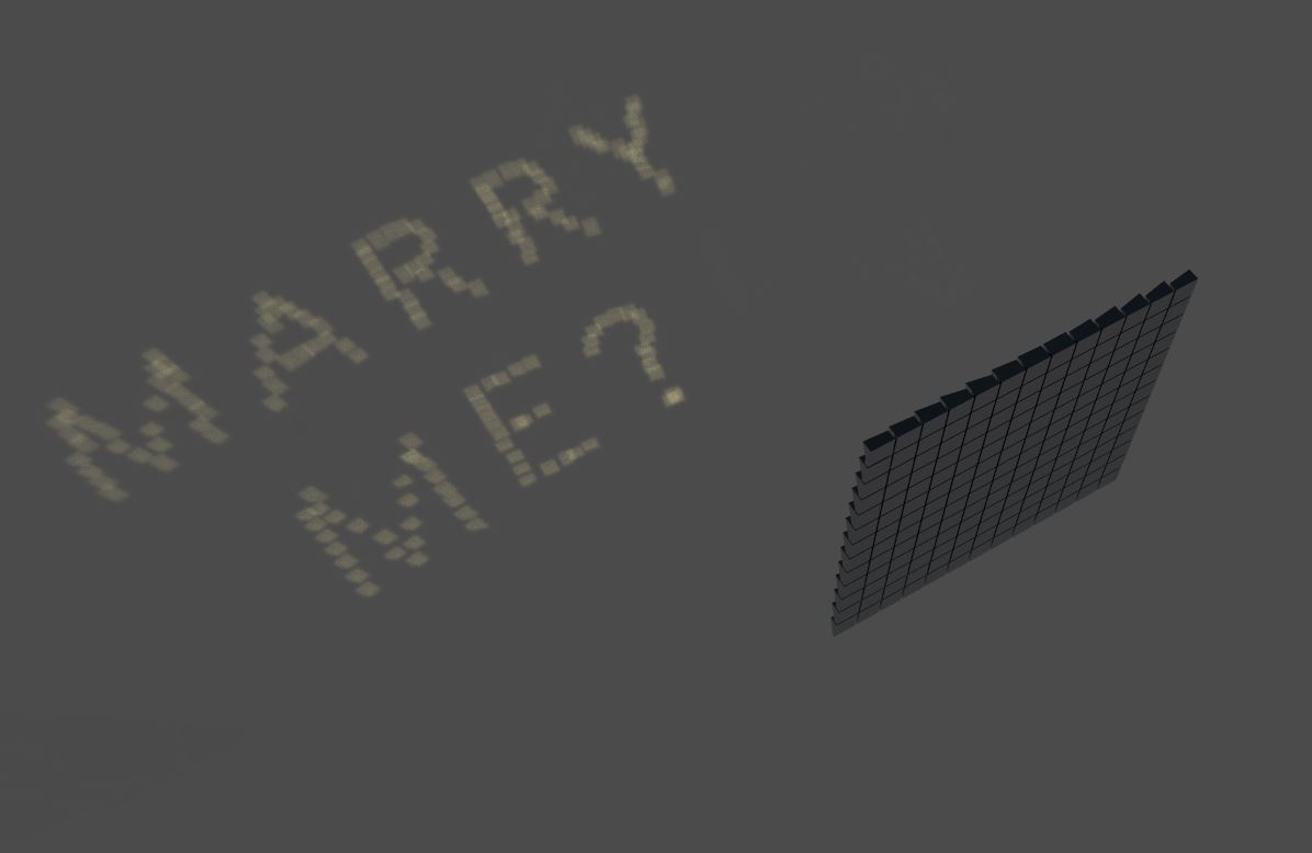
And here is the final version. After I thought about it for four weeks, it was done and ready for testing. I did a couple of tests with the individual parts; however, I could not make out anything with just one section alone. Perhaps that was a clue to how the final version would come out, but who listens to logic? Hopes and dreams beat all, right?
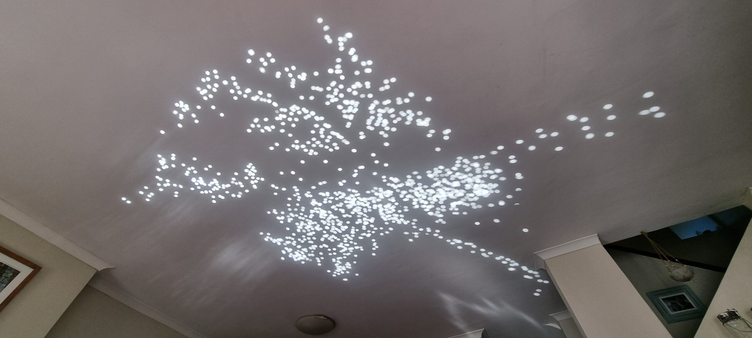
Well here is the light being reflected. If you squint your eyes and tilt your head, you can just about make out a “M E ?” at the bottom, with the “MARRY” being more “starry” than actual words!
Well, it’s time to pull out the old French dictionary and describe how I felt at that stage!
Well I figured… perhaps gluing the part together might have caused each section to have a slight misalignment, and I just needed to make one part that I can print in a single go to avoid any misalignment issues. Yes, that must be the issue, must be. However, this time I had way fewer “pixels” to play with. In previous versions I took an image and then the software placed the pixels automatically. However now I wanted full control over each pixel. As they say in “Captain Planet and the Planeteers” (yes, I’m old!)… “Me”… “Claude”… “GPT… with our powers combined we are…” Well, the below program. Dun dun dunn…
The app we made allowed me to draw an image via pixels and then convert that into a 3 d model. The one in the video still had a bug where it only affected the pixels I drew, but I wanted all mirrors to be used. Else, what is the point? I fixed that later but did not make a video of it, but you get the point.
used an old 3 D editing program called Wings 3 D and MeshLab to create borders that were 1 mm thick for the mirrors to be placed in. I was going for pure precision above all.
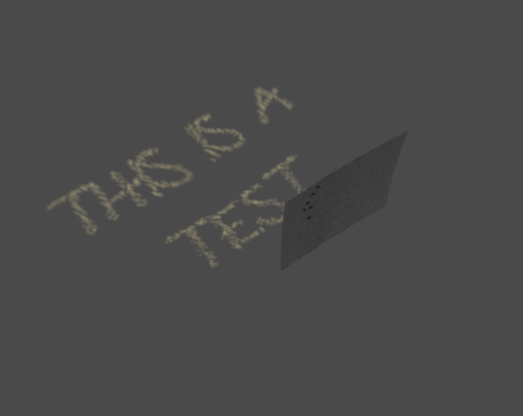
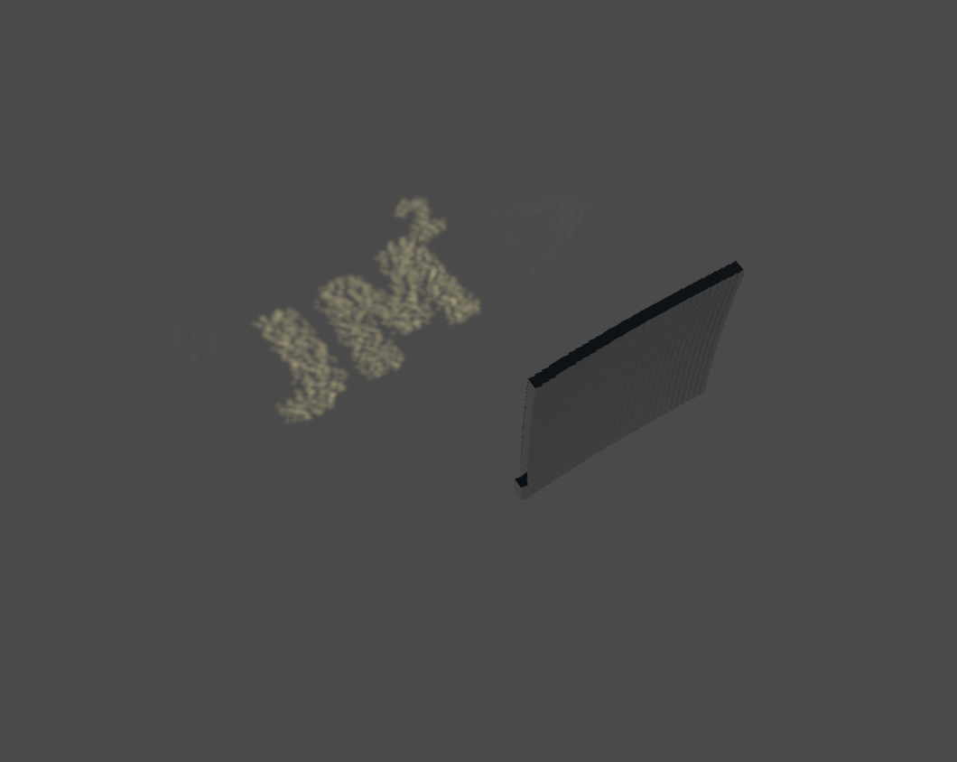
I mean, in the testing software it worked perfectly! Why would it not work in real life? Just look how amazing it looks when testing it out in the “virtual” environment.
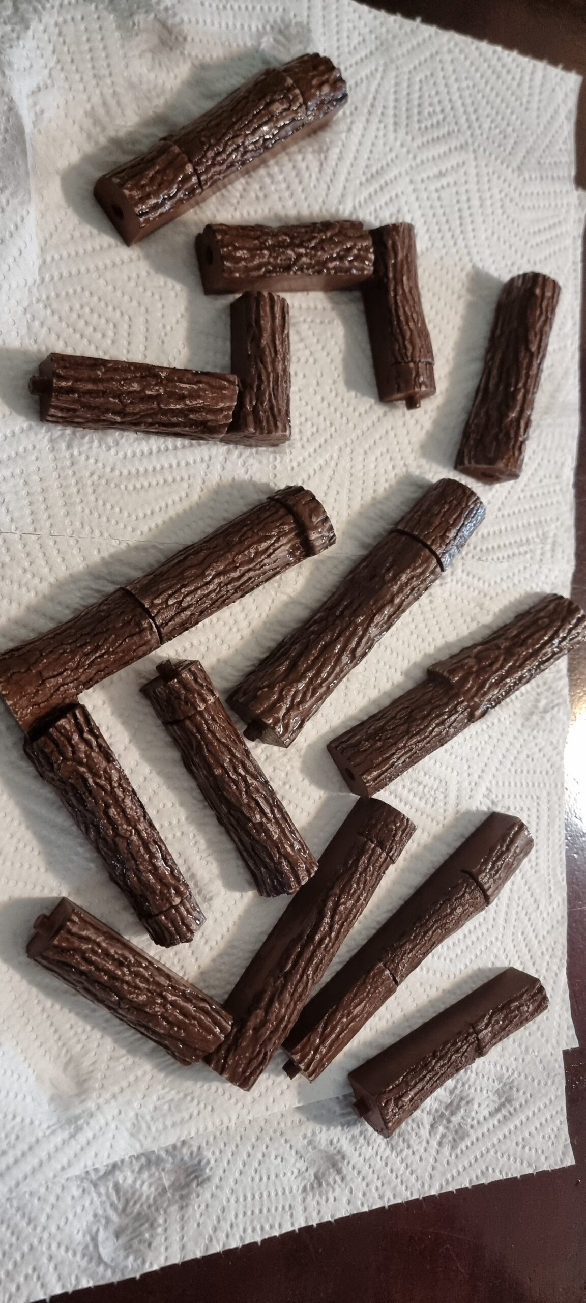
And printing we shall go… I used a nice “wood” (putting this in quotes as it does not really look like wood, hey, better than the white I’m using all the time) color this time as I’m again convinced this will be “the one”.
And here again is the final product with all the tiny mirrors stuck on. Even if it did not work, it still looks rather cool as an abstract art piece or something. Insert deep and meaningful description of the work here.
Well I will spare you the details, mostly because I did not even bother taking photos of the test above. Let’s just say you can now see random stars during the day using the above piece. This one was even worse than the large version. Thinking back, I think it might have something to do with the glue on the back of the mirrors. I mean, if we are talking about a thousandth of a millimeter, that will move one pixel 30 cm or more on the ground. I think because I did not get the glue on the back or the mirrors “flat” every time, that might have caused each mirror to be off slightly and, well, starry night! Live and learn, I guess. At this point the ring in the McDonald’s burger was looking very appealing as an option to propose.
Well at this stage I was told we were going to Betties Bay for my birthday. And this happened to be the place I was planning to ask my now fiancé to marry me. This then meant… I NOW HAVE A DEADLINE! Ok… back to basics. From what I’ve seen Ben’s version worked and from what I’ve learned printing my test failures I’m sure might get something readable even if you have to squint your eyes and be very open to interpretation. My fiancé had to go to Pretoria for a week so that left me with a couple of days where I did not have to sneak around trying to code and test things with “Marry Me” in the images. I just had enough time for one final test. I wanted to test Ben’s original design with a “JM” as test image before printing a huge part and having it end up also not working. See, I can learn!
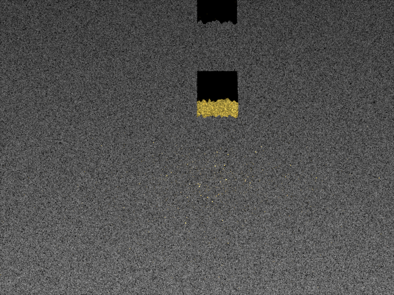
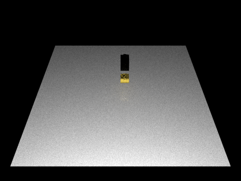
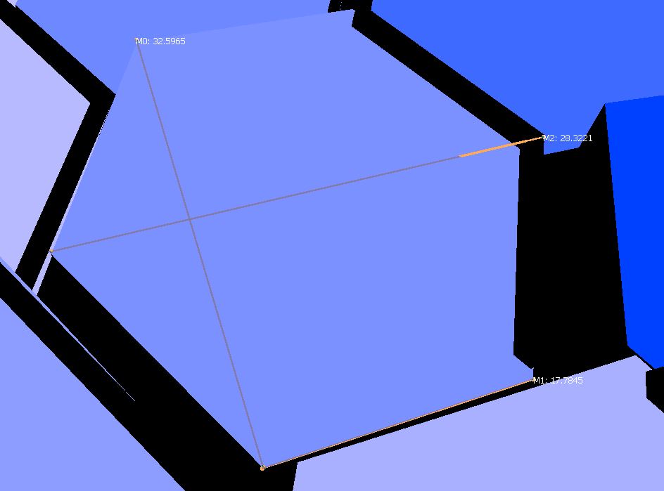
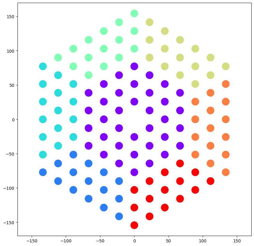
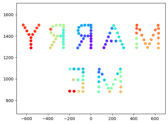
Below is the JM I was testing with with each color corresponding to where the “pixel” would be on the final 3D printed object.
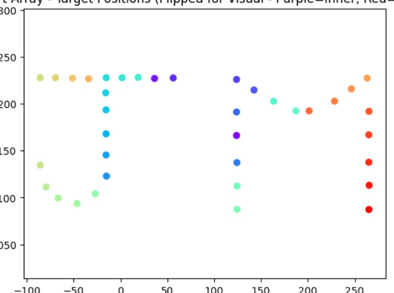
And yes, it did seem to work in the test environment, so let’s see what happens. Fingers crossed.
I made sure I knew the dimensions of how big I wanted to print the test version so I could order hexagonal mirrors the same size. Well, it was more about making the 3D model the same size as the mirrors, as there were not a lot of options to choose from. In the beginning I could not find any affordable hexagonal mirrors anywhere, but in the months after that it seems Temu had a couple of options. Who knew they sold more than just paper‑thing t‑shirts?
With time being a factor now, I ordered the mirrors and started the printing, and just hoped the size in the description was accurate. It was honestly a bit of a gamble, but it seems to have worked out in the end. The test version just managed to fit on my printed bed to print all in one part. The top layer did not look very nice, but I decided to YOLO it and ignore it. I mean, it could not be that bad, could it?
Well, the mirrors finally arrived after about 10 days, and I had to do a quick dry run. The fact that the test version said “JM” (well, supposed to) meant I could test this without raising suspicion with my fiancé. Just a nerd doing its nerdy art project. Nothing to see here.
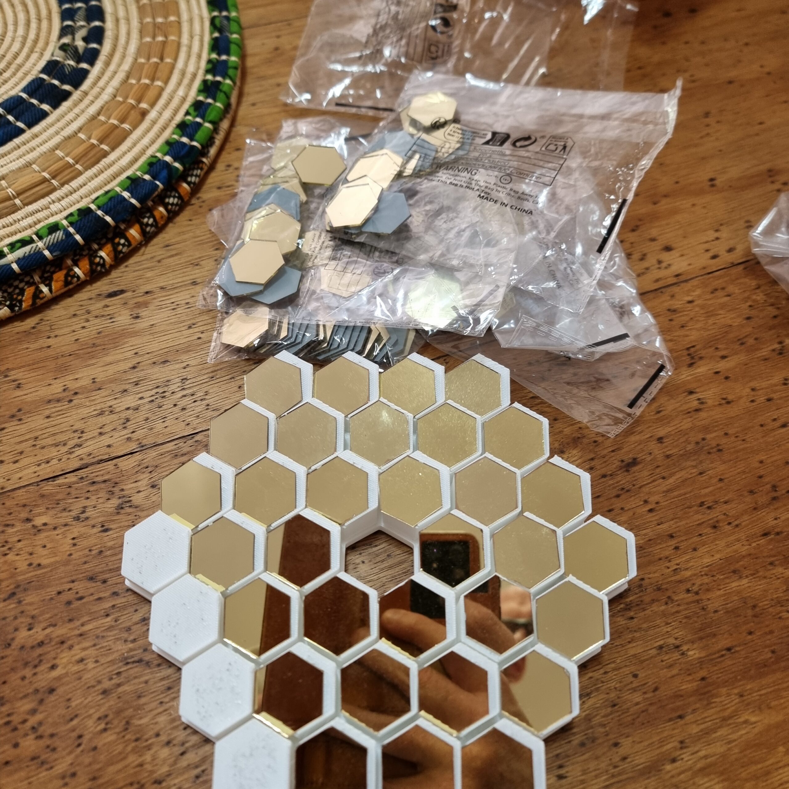
So long story short, my back of the napkin math did not work out and it seems I did not have enough mirrors for the test print and the full print. Luckily I did not glue anything yet… HAHA… who am I kidding, of course I did. What saved me was that I realized my mistake not long after super gluing the mirrors, so I could force them off with a plastic spoon without doing any damage. Thirty minutes later, and yes… not sure what I would have done.
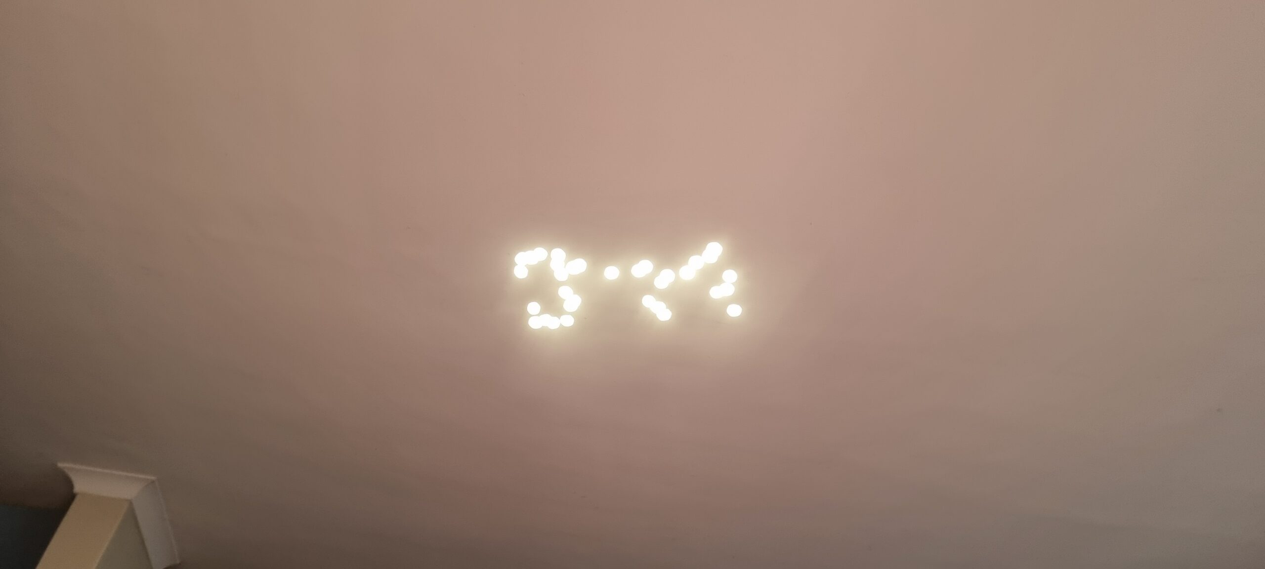
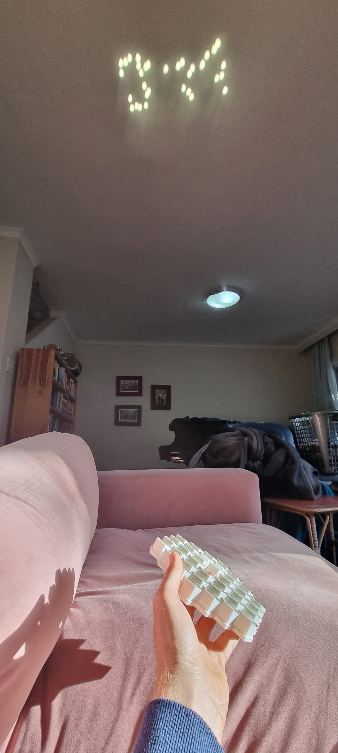
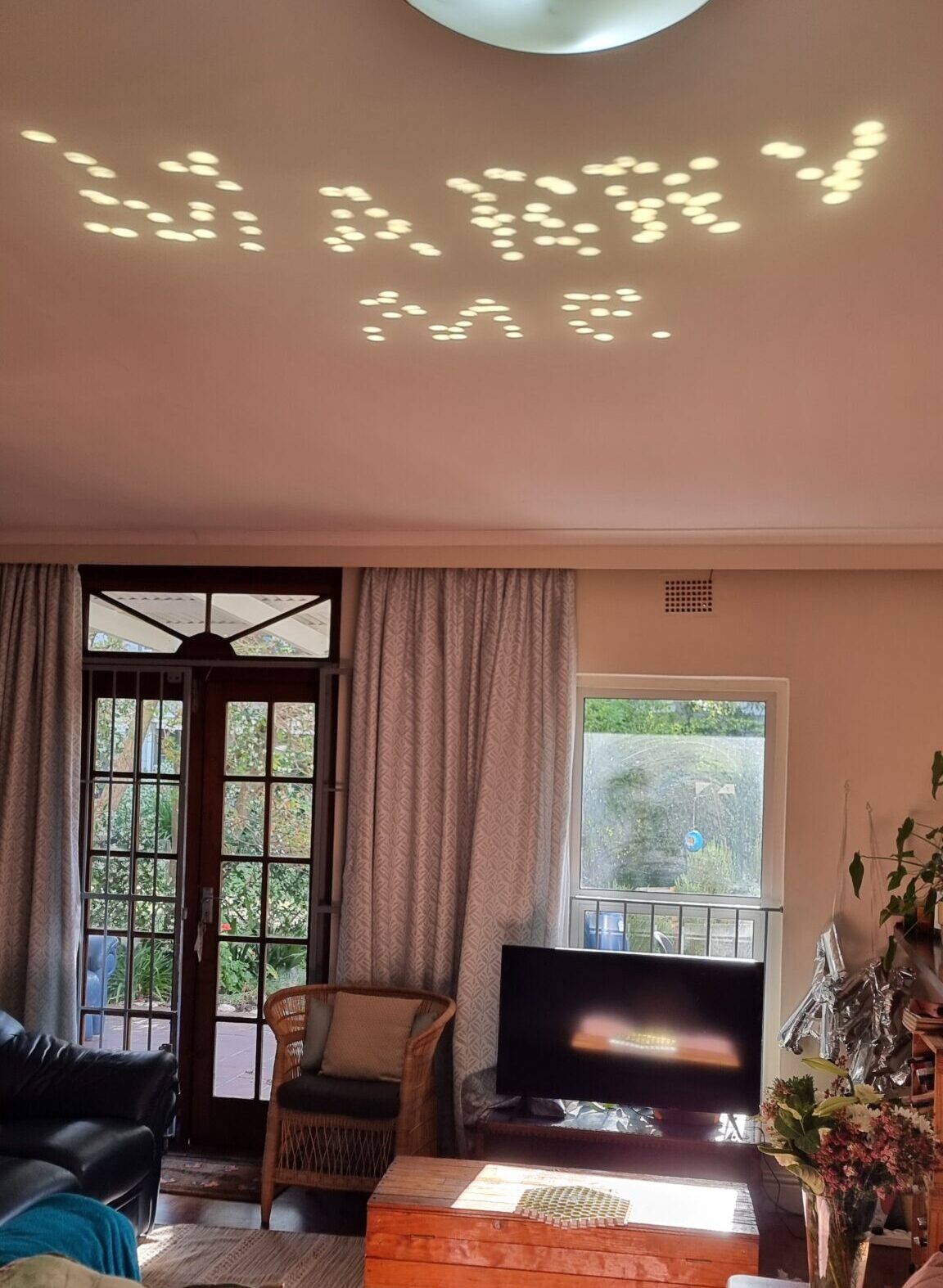
Well, after testing it out on the ceiling, you can make out the “JM” if I tell you what to look for, I guess. But I knew, and I was eureka! It works! But yes… the pixels were a bit misaligned. I am assuming this was due to the top layer of the 3d print not being completely smooth, but you know, with time running out, let’s move on to the main, and hopefully last, event!
So remember when I said I ordered the hexagonal mirrors from Temu. Well, the seller only had a limited number of mirrors, hence my test version above had two missing pixels. (1, 7, 19, 37, 61, 91, 127, 169, 217, 331, 397, 469, 547, 631, 721, 817, 919, 1027…) Well, I did not have enough to make one with 169 mirrors, so I had to modify the final pixel image to be 127 pixels in total. Now to put the pixels in the right place I had to sort of manually feel my way around with trial and error. As mentioned before, there was a way, but this involved an external website and was a bit messy. The coordinates I had to generate looked something like this:
coords = [[1394.7758146605383, 500.9562515258789], [513.1382359068762, 832.91], [968.040715759171, 447.6257155090333], [1140.7886582701574, 799.1300964355469], [1064.3186265318761, 799.9089050292969], [1521.8346177428136, 817.9267272949219], [1316.1382359068762, 825.59], [1395.2558146605384, 444.2362515258789], [1335.698235906876, 854.7], [1501.458235906876, 853.25], [1226.1258146605383, 464.5062515258789], [1520.248235906876, 763.19], [1374.6758146605382, 497.9662515258789], [1212.6558146605382, 496.1862515258789], [890.9263535826574, 418.1148681640625], [861.8482359068761, 467.27], [827.7982359068761, 466.59], [794.9282359068761, 467.39], [861.1182359068762, 366.3], [832.2082359068761, 365.58], [794.7738267271886, 257.5711669921875], [829.8958970396886, 257.8609619140625], [864.0400620787511, 258.04620361328125], [889.5782359068761, 282.62], [890.3182359068761, 310.38], [891.5682603209386, 340.74298095703125]…. and so on
Seeing that I had to update the MARRY ME, I needed a way to iterate faster. Claude, come on down and do your magic. After I think five or six back and forth I had a tool that I was happy with and that you can see below in action. This allowed me to add, remove, move, flip any points to my heart’s content. This way I could update the text to be exactly 127 points and still make sense. I had to lose the question mark in the process, but I assumed when she saw “Marry Me” she would know what my intentions were.
So now I present you the final version, and at this point I must admit it would have been the final version, whether it worked or not.
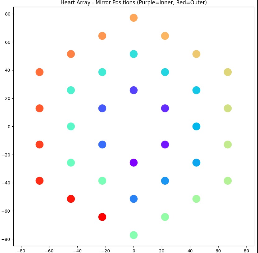
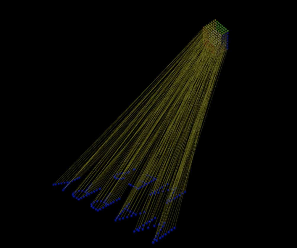
Here is another image directly from Ben’s notebook. Here you can see how each point links to the pixel that is supposed to be displayed on the ground. Pretty amazing even after seeing it after so many months and knowing how it works.
I had to again test the final 3D model and also make sure I knew what section went where. Here is a screenshot of the “guide” I made by coloring in some of the sections so that I don’t lose track of what goes where. Ben was also smart enough to add some guides and I used them to align everything. I assume they were also there to keep the mirrors in place, but I must have messed up the code somewhere as the holders / guides were on the left rather than the bottom. Nonetheless they did their job.
Here is the final final super last please work fin fin help me really last version before sending it off to the printer. Yes, I had more than 40 versions at this point, and hopefully this was the last one.
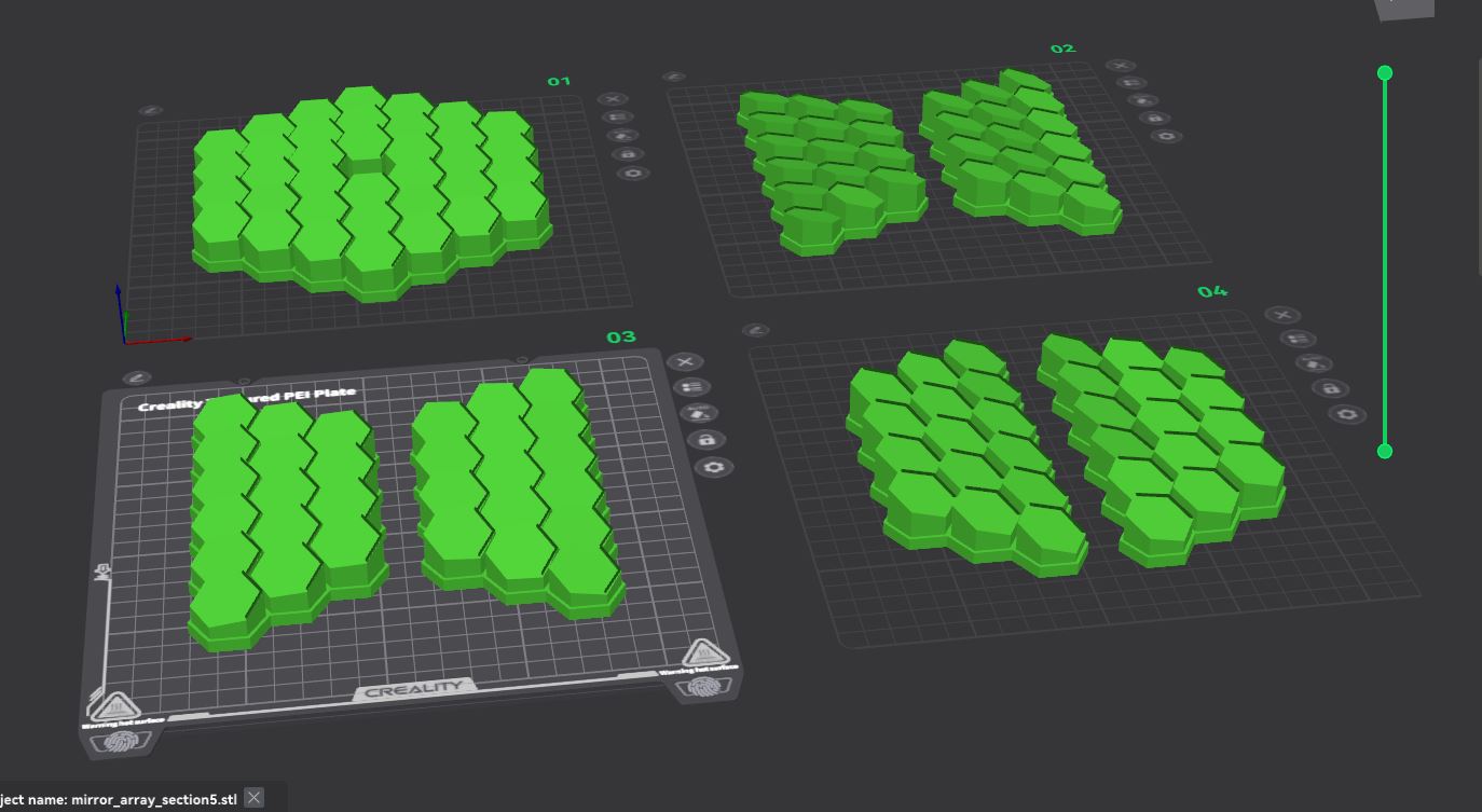
I made sure I marked what section goes on what plate so when I printed it I could keep track and mark them on the back. This took about 3 days to print as each print was between six and 12 hours long. Also, you know I had to go to work, sleep, and other stuff you need to do to keep on living.
And here are all the prints done. I will say I did stare at them for a while just thinking that this was all done with code! Ben’s math skills are definitely a bit above my comprehension, but I had a lot of fun trying to make sense of it.
I also realized I would need to make something to keep all the parts in place. I wanted to just put it on a board or just glue the parts as is, however I did not want to risk me bumping it and breaking off a part by accident. So I designed this bracket, holder, abstract art thing to hold everything into place. I removed a lot of material since I did not want to waste 3D filament and nobody will see this. So as long as it was still structurally good, I was happy.
Did you know super glue does not stick to wax paper? Thanks GPT! This saved my table and my fingers from being acquainted with a lot of things they should not need. I split the part into four sections to fit on my 3d printed surface and then glued each part one at a time.
As with any 3D print, nothing is the same as the 3D model and there was a gap on one side. So I used some leftover 3D printing filament to fill in the gap and make sure the part was secure and sturdy before trying to add the actual 3D parts onto it.
And here you have the final backing. It kind of felt like a toy you wanted to throw at someone.
And now for the assembly! This is a video of me testing to see if everything would fit. Given my track record of just trying stuff and hoping it would work, I surprised myself by thinking ahead a little bit and printed the base 0.5 mm larger than what I designed it for. Since I used a lot of Boolean operations to create the base, it would fit super snug with zero tolerance. And you can see from the video it clicked into place with much satisfaction. You will also see there were some “dots” on some of the parts. This was one of my ideas to align the mirrors afterwards. The idea I had was to stick the mirrors on the Prestik so it had some movement that I could then later use to align each pixel one at a time. Good idea, but as we all now know… not so good in practice. Turns out adding Prestik misaligned the mirrors so much I did not have a starting image to work off and had no idea what pixel is supposed to go where. Yes, I had the reference image; however, even I, with somewhat decent 3 D perception, was unable to play 4 D chess and gave up after about 30 min in the sun.
Here is a close up of the final printed part. Some numbers were for me to make sure the right parts go in the right places. You can see the top layer was not very well printed and I’m sure if I had more time I could have played with the printer settings to get a smooth top surface, however time was running out quickly and D Day was just around the corner.
So what did I do? I spent an entire weekend sanding all my fingerprints (no really!) off? Yes, that is what I did. The idea was to try and remove any bumps that formed during the printing process, so that at least in theory this would help in aligning the mirrors to where they should point.
Well, one weekend (OK, it was about 6 hours, but still) later, I have a much smoother surface that would hopefully help in getting the message across. Pun intended…?
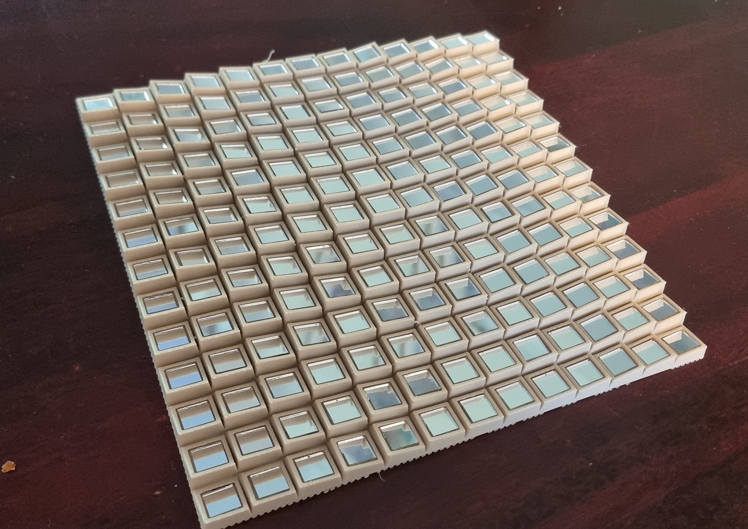
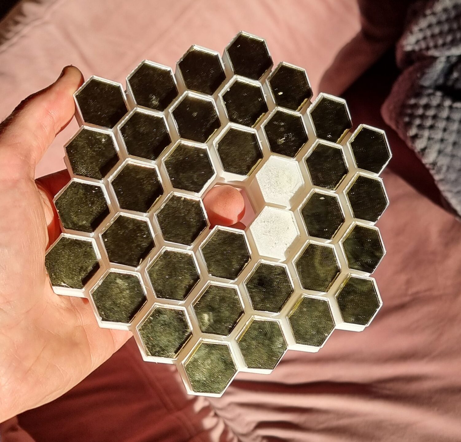
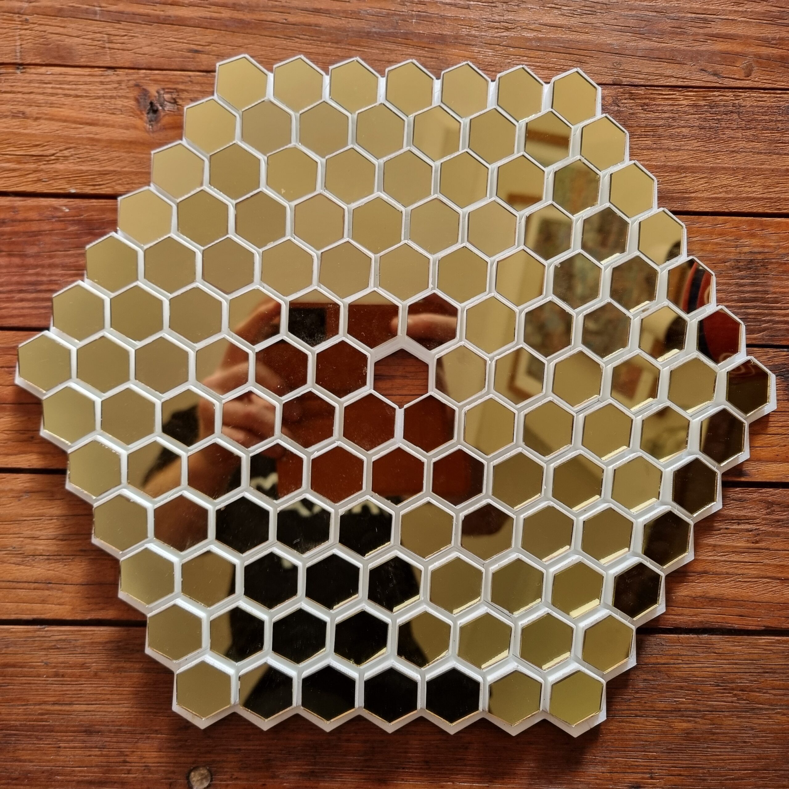
And here you see the final result. Besides tiny mirrors, sandpaper, super glue is now also on my list of things I don’t want to see or smell for the next couple of years. But I think it was all worth it. Looks pretty cool, I must say. This is 99 % Ben’s design, so don’t give me any credit here. The only thing I did was reduce the number of hexagons from the original design.
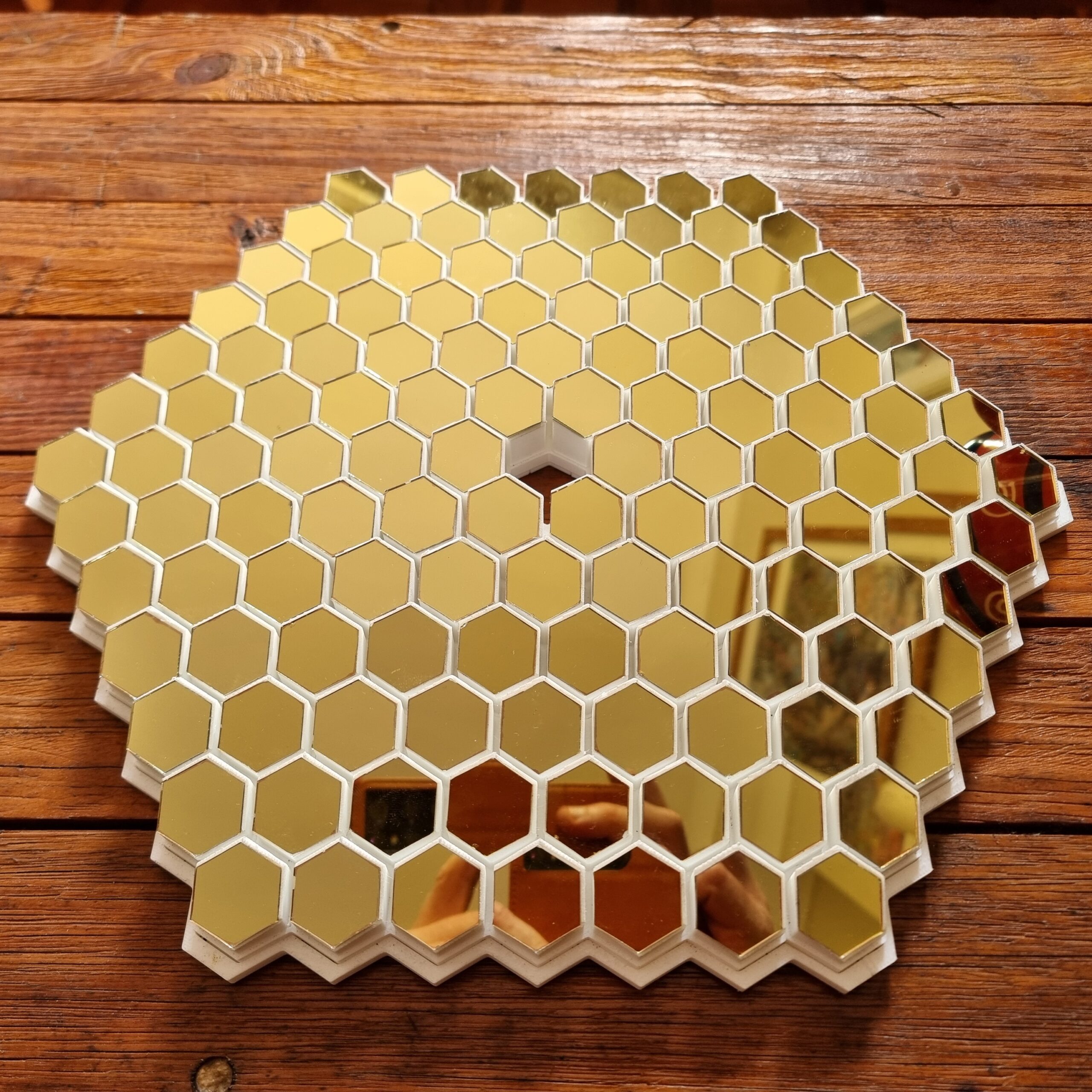
So at last, it seems I had some success. Sometimes reinventing the wheel will just waste months of work and cause you to rethink your life choices. Well, at least the method of proposal. Other life choices I’m very happy with, thank you very much. I did this test when my fiancé was upstairs, so I had to test it very quickly and then pack it away again.
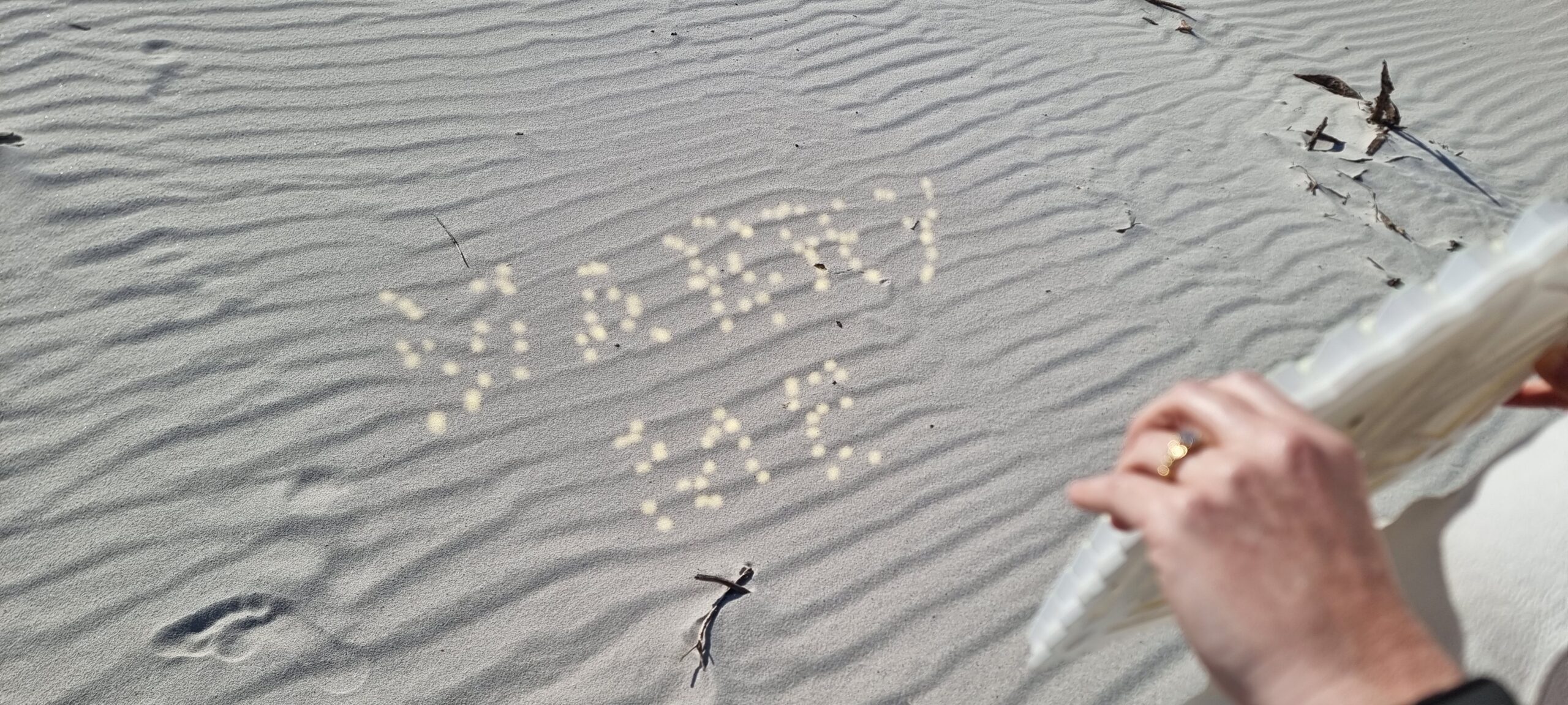
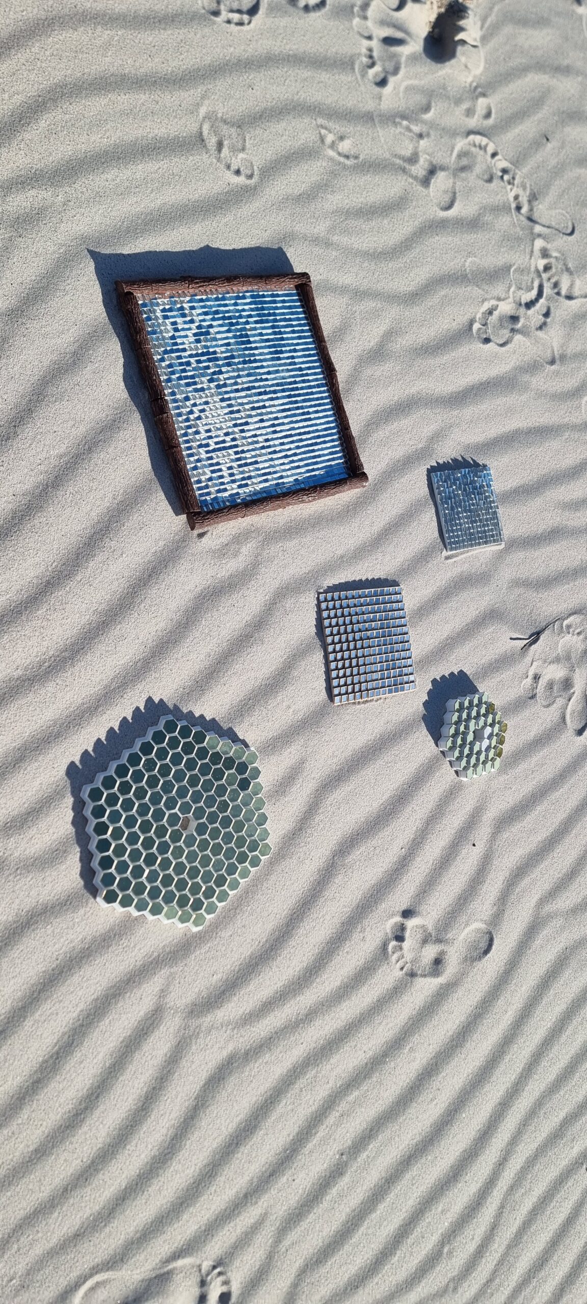
So on the big day, or shall I say week, as I did not know precisely what day I would propose due to the weather being a factor, I asked my fiancé if she would pose with all my “art projects” just so that I can post it. I started off with a couple of the failed ones because I knew no message would be reflected. Then I handed her the “final” one that I kept as a surprise for her. Well, the sand made the letters a little bit more distorted, but you know what… SHE SAID YES!!! And in the end that is all that counted, and still better than a ring in a McDonald’s burger.
Any proposal needs a ring, and although this article is about how I made the mirrors, I thought I would also share the ring I designed. Another reason is that the whole process took seven or eight months.
If you feel you want to have a look at my super professional code that is totally git versioned and not just copy-1.py, copy-2.py, copy-3.py etc. (Kidding! It totally is!) Let me know